
Page 124 - Defrosting for Air Source Heat Pump
P. 124
Investigation of effect on uneven defrosting performance 117
Side A (Topside)
44 mm Side B
590 mm
(Back side)
Circuit 1
Side C (Front side) Circuit 3
mm 500 mm
500 Circuit 2 Circuit 2
Side C
Circuit 1
(Downside)
Circuit 3 44 mm
Side B Side A 590 mm
(Downside) (Front side)
(A) (B)
Refrigerantout Circuit 1 Refrigerant out
500 mm Flow direction of hot refrigerant Flow direction of cold melted frost Circuit 2 Flow direction of cold melted frost
Refrigerant in Circuit 3 Flow direction of hot refrigerant
500 mm
Refrigerant in
(C) (D)
Circuit 3
44 mm Side B 500 mm Circuit 2
590 mm
Side C
Circuit 1
590 mm
(E) (F)
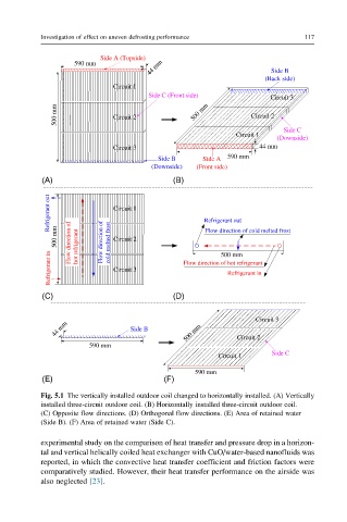
Fig. 5.1 The vertically installed outdoor coil changed to horizontally installed. (A) Vertically
installed three-circuit outdoor coil. (B) Horizontally installed three-circuit outdoor coil.
(C) Opposite flow directions. (D) Orthogonal flow directions. (E) Area of retained water
(Side B). (F) Area of retained water (Side C).
experimental study on the comparison of heat transfer and pressure drop in a horizon-
tal and vertical helically coiled heat exchanger with CuO/water-based nanofluids was
reported, in which the convective heat transfer coefficient and friction factors were
comparatively studied. However, their heat transfer performance on the airside was
also neglected [23].