
Page 128 - Defrosting for Air Source Heat Pump
P. 128
Investigation of effect on uneven defrosting performance 121
upward surface of the outdoor coil, the opposite side to Side C, so that the measured fin
surface temperatures can avoid the effects of downward-flowing melted frost during
defrosting. Furthermore, one more thermocouple was placed inside the water-
collecting cylinder to measure the temperature of the melted frost collected, as shown
in Fig. 5.2. On the other hand, for the experimental ASHP unit, refrigerant pressures
were measured using pressure transmitters (Danfoss Pressure Transmitter, Type AKS
32 and AKS 33) with an accuracy of 0.3% of full scale reading and refrigerant vol-
umetric flow rate by a variable area flow meter with a reported accuracy of 1.6% of
full scale reading (KROHNE VA Flowmeter, H250). All sensors and measuring
devices were able to output a direct current signal of 4–20 mA or 1–5 V, which
can be transferred to a data acquisition system (DAS) for logging and recording.
The DAS collected and recorded all the measured data throughout both frosting
and defrosting at an interval of 5 s. In addition, during defrosting, photos for surface
conditions of the outdoor coil were taken at an interval of 10 s.
5.2.1.2 Experimental procedures and conditions
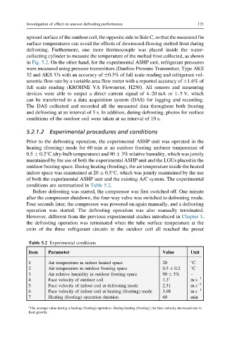
Prior to the defrosting operation, the experimental ASHP unit was operated in the
heating (frosting) mode for 60 min at an outdoor frosting ambient temperature of
0.5 0.2°C (dry-bulb temperature) and 90 3% relative humidity, which was jointly
maintained by the use of both the experimental ASHP unit and the LGUs placed in the
outdoor frosting space. During heating (frosting), the air temperature inside the heated
indoor space was maintained at 20 0.5°C, which was jointly maintained by the use
of both the experimental ASHP unit and the existing A/C system. The experimental
conditions are summarized in Table 5.2.
Before defrosting was started, the compressor was first switched off. One minute
after the compressor shutdown, the four-way valve was switched to defrosting mode.
Four seconds later, the compressor was powered on again manually, and a defrosting
operation was started. The defrosting operation was also manually terminated.
However, different from the previous experimental studies introduced in Chapter 3,
the defrosting operation was terminated when the tube surface temperature at the
exits of the three refrigerant circuits in the outdoor coil all reached the preset
Table 5.2 Experimental conditions
Item Parameter Value Unit
1 Air temperature in indoor heated space 20 °C
2 Air temperature in outdoor frosting space 0.5 0.2 °C
3 Air relative humidity in outdoor frosting space 90 3% –
4 Face velocity of outdoor coil 1.3 a ms 1
5 Face velocity of indoor coil at defrosting mode 2.31 m s 1
6 Face velocity of indoor coil at heating (frosting) mode 3.68 m s 1
7 Heating (frosting) operation duration 60 min
a
The average value during a heating (frosting) operation. During heating (frosting), the face velocity decreased due to
frost growth.