
Page 126 - Defrosting for Air Source Heat Pump
P. 126
Investigation of effect on uneven defrosting performance 119
To compressor Heating mode Side B
From compressor To EEV Defrosting mode
From EEV
Header 650 mm
44 mm
T e
Circuit 3
MV 3
T i
SV 3
T e
Circuit 2 Wind board
MV 2 326 mm
T i Side C
SV 2 Meltedfrost
T e 700 mm
Circuit 1
MV 1 22 mm
T i
SV 1 152 mm
Distributor 590 mm
Side A Melted frost
750 mm
Water collecting tray Water collecting cylinder
(slope 37 ) (2000 mL)
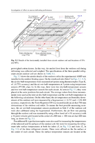
Fig. 5.2 Details of the horizontally installed three-circuit outdoor coil and locations of SVs
and MVs.
preweighed cotton tissues. In this way, the melted frost from the outdoor coil during
defrosting was collected and weighed. The specifications of the three-parallel refrig-
erant circuit outdoor coil are shown in Table 5.1.
Fig. 5.3 shows the airside details of the outdoor coil in the experimental ASHP unit
installed in the outdoor frosting space. On the windward side (Side C in Figs. 5.1–5.3),
the air dry-bulb temperatures were measured at 6 points using thermocouples (Type K,
of 0.75% accuracy) and the air wet-bulb temperatures at 3 points using temperature
sensors (PT100, class A). In this way, there were two dry-bulb temperature sensors
and two wet-bulb temperature sensors for each circuit. As seen in Fig. 5.3, they were
placed at the same positions for each circuit. The average values from these measure-
ments were used as the inlet air dry-bulb temperature and the wet-bulb temperature in
the following calculations. On the other hand, the air temperature and humidity down-
stream of the outdoor coil were measured by a hygrosensor ( 0.2°C and 1.0% RH
accuracy, respectively; the Testo Hygrotest 650 was located inside an air duct 700 mm
downstream of the outdoor coil outlet. To ensure the best possible measuring accu-
racy, the air wet-bulb temperature sensors positioned on Side C of the outdoor coil
were also calibrated using the hygrosensor. Furthermore, the air flow rate passing
through the outdoor coil was measured by using a flow hood (of 3% accuracy) with
a 16-point velocity grid located at the center of a 400 mm 400 mm air duct 600 mm
long, as shown in Fig. 5.3.
Precalibrated K-type thermocouples were also used for measuring the temperatures
of the tube/coil and fin surfaces of the outdoor coil. Six were for measuring the refrig-
erant tube surface temperatures at both the inlets (T i in Fig. 5.2) and exits (T e in
Fig. 5.2) of the three refrigerant circuits. Three were affixed on the fin surface at
the center of each circuit. These fin surface temperature sensors are located at the