
Page 131 - Defrosting for Air Source Heat Pump
P. 131
124 Defrosting for Air Source Heat Pump
Fin Fin
Vaporizing due to Vaporizing due to
heating from fins heating from fins
Droplets Droplets
Freely flowing Freely flowing due to gravity
due to gravity and blowing the water away
(A) (B)
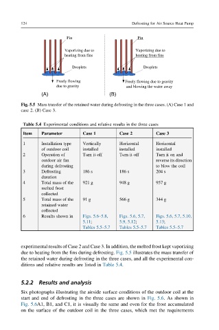
Fig. 5.5 Mass transfer of the retained water during defrosting in the three cases. (A) Case 1 and
case 2. (B) Case 3.
Table 5.4 Experimental conditions and relative results in the three cases
Item Parameter Case 1 Case 2 Case 3
1 Installation type Vertically Horizontal Horizontal
of outdoor coil installed installed installed
2 Operation of Turn it off Turn it off Turn it on and
outdoor air fan reverse its direction
during defrosting to blow the coil
3 Defrosting 186 s 186 s 204 s
duration
4 Total mass of the 921 g 948 g 957 g
melted frost
collected
5 Total mass of the 91 g 566 g 344 g
retained water
collected
6 Results shown in Figs. 5.6–5.8, Figs. 5.6, 5.7, Figs. 5.6, 5.7, 5.10,
5.11; 5.9, 5.12; 5.13;
Tables 5.5–5.7 Tables 5.5–5.7 Tables 5.5–5.7
experimental results of Case 2 and Case 3. In addition, the melted frost kept vaporizing
due to heating from the fins during defrosting. Fig. 5.5 illustrates the mass transfer of
the retained water during defrosting in the three cases, and all the experimental con-
ditions and relative results are listed in Table 5.4.
5.2.2 Results and analysis
Six photographs illustrating the airside surface conditions of the outdoor coil at the
start and end of defrosting in the three cases are shown in Fig. 5.6. As shown in
Fig. 5.6A1, B1, and C1, it is visually the same and even for the frost accumulated
on the surface of the outdoor coil in the three cases, which met the requirements