
Page 154 - Defrosting for Air Source Heat Pump
P. 154
Investigation of effect on uneven defrosting performance 147
5.3.3 Discussions and energy analysis
Due to the surface tension, there would be melted frost retained on the downside sur-
face of the outdoor coil. In addition, the mass of the remaining melted frost is posi-
tively proportional with the area of remaining water, as shown in Fig. 5.14. However,
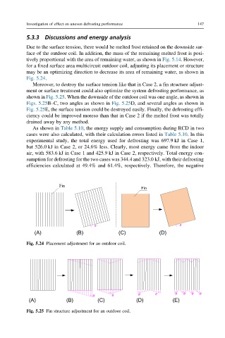
for a fixed surface area multicircuit outdoor coil, adjusting its placement or structure
may be an optimizing direction to decrease its area of remaining water, as shown in
Fig. 5.24.
Moreover, to destroy the surface tension like that in Case 2, a fin structure adjust-
ment or surface treatment could also optimize the system defrosting performance, as
shown in Fig. 5.25. When the downside of the outdoor coil was one angle, as shown in
Figs. 5.25B–C, two angles as shown in Fig. 5.25D, and several angles as shown in
Fig. 5.25E, the surface tension could be destroyed easily. Finally, the defrosting effi-
ciency could be improved moreso than that in Case 2 if the melted frost was totally
drained away by any method.
As shown in Table 5.10, the energy supply and consumption during RCD in two
cases were also calculated, with their calculation errors listed in Table 5.10. In this
experimental study, the total energy used for defrosting was 697.9 kJ in Case 1,
but 526.0 kJ in Case 2, or 24.6% less. Clearly, most energy came from the indoor
air, with 583.6 kJ in Case 1 and 425.9 kJ in Case 2, respectively. Total energy con-
sumption for defrosting for the two cases was 344.4 and 323.0 kJ, with their defrosting
efficiencies calculated at 49.4% and 61.4%, respectively. Therefore, the negative
Fin
Fin
q q
(A) (B) (C) (D)
Fig. 5.24 Placement adjustment for an outdoor coil.
q q q q q q q q
(A) (B) (C) (D) (E)
Fig. 5.25 Fin structure adjustment for an outdoor coil.