
Page 59 - Defrosting for Air Source Heat Pump
P. 59
50 Defrosting for Air Source Heat Pump
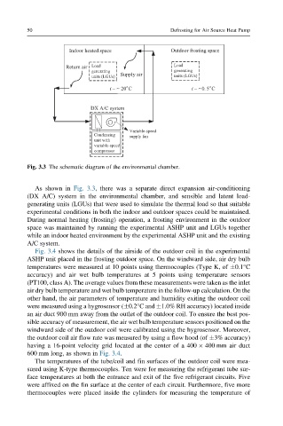
Fig. 3.3 The schematic diagram of the environmental chamber.
As shown in Fig. 3.3, there was a separate direct expansion air-conditioning
(DX A/C) system in the environmental chamber, and sensible and latent load-
generating units (LGUs) that were used to simulate the thermal load so that suitable
experimental conditions in both the indoor and outdoor spaces could be maintained.
During normal heating (frosting) operation, a frosting environment in the outdoor
space was maintained by running the experimental ASHP unit and LGUs together
while an indoor heated environment by the experimental ASHP unit and the existing
A/C system.
Fig. 3.4 shows the details of the airside of the outdoor coil in the experimental
ASHP unit placed in the frosting outdoor space. On the windward side, air dry bulb
temperatures were measured at 10 points using thermocouples (Type K, of 0.1°C
accuracy) and air wet bulb temperatures at 5 points using temperature sensors
(PT100, class A). The average values from these measurements were taken as the inlet
air dry bulb temperature and wet bulb temperature in the follow-up calculation. On the
other hand, the air parameters of temperature and humidity exiting the outdoor coil
were measured using a hygrosensor ( 0.2°C and 1.0% RH accuracy) located inside
an air duct 900 mm away from the outlet of the outdoor coil. To ensure the best pos-
sible accuracy of measurement, the air wet bulb temperature sensors positioned on the
windward side of the outdoor coil were calibrated using the hygrosensor. Moreover,
the outdoor coil air flow rate was measured by using a flow hood (of 3% accuracy)
having a 16-point velocity grid located at the center of a 400 400 mm air duct
600 mm long, as shown in Fig. 3.4.
The temperatures of the tube/coil and fin surfaces of the outdoor coil were mea-
sured using K-type thermocouples. Ten were for measuring the refrigerant tube sur-
face temperatures at both the entrance and exit of the five refrigerant circuits. Five
were affixed on the fin surface at the center of each circuit. Furthermore, five more
thermocouples were placed inside the cylinders for measuring the temperature of