
Page 57 - Defrosting for Air Source Heat Pump
P. 57
48 Defrosting for Air Source Heat Pump
3.2.1 Experimental setup
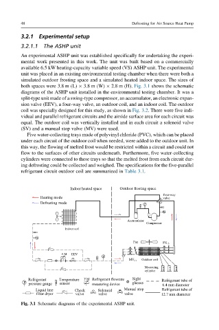
3.2.1.1 The ASHP unit
An experimental ASHP unit was established specifically for undertaking the experi-
mental work presented in this work. The unit was built based on a commercially
available 6.5 kW heating-capacity variable speed (VS) ASHP unit. The experimental
unit was placed in an existing environmental testing chamber when there were both a
simulated outdoor frosting space and a simulated heated indoor space. The sizes of
both spaces were 3.8 m (L) 3.8 m (W) 2.8 m (H). Fig. 3.1 shows the schematic
diagrams of the ASHP unit installed in the environmental testing chamber. It was a
split-type unit made of a swing-type compressor, an accumulator, an electronic expan-
sion valve (EEV), a four-way valve, an outdoor coil, and an indoor coil. The outdoor
coil was specially designed for this study, as shown in Fig. 3.2. There were five indi-
vidual and parallel refrigerant circuits and the airside surface area for each circuit was
equal. The outdoor coil was vertically installed and in each circuit a solenoid valve
(SV) and a manual stop valve (MV) were used.
Five water-collecting trays made of polyvinyl chloride (PVC), which can be placed
under each circuit of the outdoor coil when needed, were added to the outdoor unit. In
this way, the flowing of melted frost would be restricted within a circuit and could not
flow to the surfaces of other circuits underneath. Furthermore, five water-collecting
cylinders were connected to these trays so that the melted frost from each circuit dur-
ing defrosting could be collected and weighed. The specifications for the five-parallel
refrigerant circuit outdoor coil are summarized in Table 3.1.
Fig. 3.1 Schematic diagrams of the experimental ASHP unit.