
Page 88 - Defrosting for Air Source Heat Pump
P. 88
80 Defrosting for Air Source Heat Pump
q Me q T,j
L sf,m f,j
Refrigerant Coil Water Frost
(a) Stage 1 Ambient air
(All control volumes) T w,j
layer
metal
h c,w(T w,j –T a)A w-a
q Me q T,j
Refrigerant Coil Water Frost
(b) Stage 2 L sf,m f,j
(All control volumes) T w,j Ambient air
layer
metal
q Me q T,1
h c,w(T w,1 –T a)A w-a
Refrigerant Coil layer L sf,m f,1
T w,1
CV 1 Water Ambient air
metal
Frost
c pm w,1T w,1 (to Circuit 2)
c pm w,1T w,1 (from Circuit 1)
q Me q T,2
h c,w(T w,2 –T a)A w-a
T w,2
(c) Stage 3 Refrigerant Coil Water L sf,m f,2 Ambient air
CV 2
layer
metal
Frost
c pm w,2T w,2 (to Circuit 3)
c pm w,2T w,2 (from Circuit 2)
q Me q T,3
h c,w(T w,3 –T a)A w-a
Refrigerant Coil layer L sf,m f,3
T w,3
CV 3 Water Ambient air
metal
Frost
c pm w,3T w,3 (to Tray C)
h c,d (T r,j –T a)A d-a
q Me
Refrigerant Coil Water
(d) Stage 4 q T,j h c,w(T w,j –T a)A w-a
(All control volumes) T w,j m v,jL v Ambient air
layer
metal
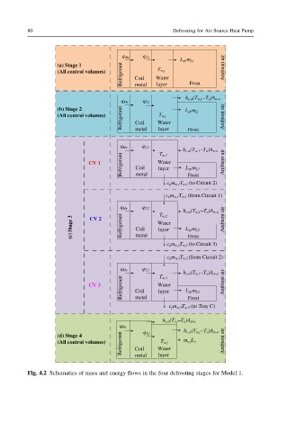
Fig. 4.2 Schematics of mass and energy flows in the four defrosting stages for Model 1.