
Page 93 - Defrosting for Air Source Heat Pump
P. 93
Modeling study on uneven defrosting 85
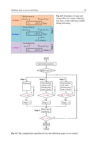
(From Circuit j) Fig. 4.4 Schematics of mass and
c pm w,jT w,j h cA tw(T a-T tw) energy flows in a water-collecting
(a) Step 1 tray and a water-collecting cylinder
T tw c pM twT tw Tray j during defrosting.
(From Circuit j)
Stage 3
c pm w,jT w,j h cA tw(T a-T tw)
(b) Step 2 T tw c pM twT tw Tray j
c pm cT tw
(To Cylinder j)
(To ambient air)
m v,twL v h cA tw(T a-T tw) Stage 4
(c) Step 3
T tw c pM twT tw Cylinder j
Start
Input initial parameters
Initial Stage = 1
Stage 1 Stage 2 Stage 3
Preheating Frost melting Frost melting
without water with water
flowing away flowing away
from a circuit from a circuit
N N N
t 40 s t 90 s M f,j 1050 g
Y Y Y
Stage = 2 Stage = 3 Stage = 4
Water layer
Stage 4
vaporizing
N
o
24 C
T e,3
Y
Outputs
End
Fig. 4.5 The computational algorithm for the four defrosting stages in two models.