
Page 170 - Design and Operation of Heat Exchangers and their Networks
P. 170
158 Design and operation of heat exchangers and their networks
Finely dispersed bubble
10
C
B
Annular
1
Bubble E
j l (m/s) 500
200
0.1
A 100
l /d =50
E
Churn
Slug
0.01
D
0.01 0.1 1 10 100
(m/s)
j g
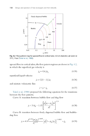
Fig. 4.2 Flow pattern map for upward flow in vertical tube, 5.0-cm diameter, air-water at
25°C, 1bar (Taitel et al., 1980).
upward flow in vertical tubes, the flow pattern regimes are shown in Fig. 4.2,
in which the superficial gas velocity is
j g ¼ G _x=ρ g (4.35)
superficial liquid velocity
j l ¼ G 1 _xð Þ=ρ l (4.36)
and mixture volumetric flux
(4.37)
j ¼ j l + j g
Taitel et al. (1980) proposed the following equations for the transitions
between the flow patterns.
Curve A: transition between bubble flow and slug flow
31=4
2
g ρ ρ σ
g
l
j l ¼ 3:0j g 1:15 4 5 (4.38)
ρ 2
l
Curve B: transition between finely dispersed bubble flow and bubble-
slug flow
d 0:429 ð σ=ρ Þ 0:0895 h i 0:4465
l
j l ¼ 4:0 g 1 ρ =ρ l j g (4.39)
g
ν 0:072
l