
Page 171 - Design and Operation of Heat Exchangers and their Networks
P. 171
Thermal design of evaporators and condensers 159
2
2
3
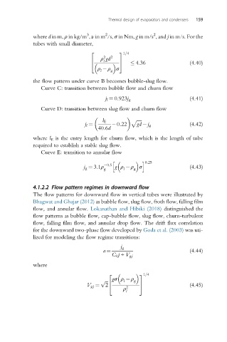
where d in m, ρ in kg/m , ν in m /s, σ in Nm, g in m/s , and j in m/s. For the
tubes with small diameter,
2 3 1=4
2
ρ gd 2
4 l 5 4:36 (4.40)
ρ ρ σ
l
g
the flow pattern under curve B becomes bubble-slug flow.
Curve C: transition between bubble flow and churn flow
j l ¼ 0:923j g (4.41)
Curve D: transition between slug flow and churn flow
l E p ffiffiffiffiffi
j l ¼ 0:22 gd j g (4.42)
40:6d
where l E is the entry length for churn flow, which is the length of tube
required to establish a stable slug flow.
Curve E: transition to annular flow
h i 0:25
j g ¼ 3:1ρ 0:5 g ρ ρ σ (4.43)
g
g
l
4.1.2.2 Flow pattern regimes in downward flow
The flow patterns for downward flow in vertical tubes were illustrated by
Bhagwat and Ghajar (2012) as bubble flow, slug flow, froth flow, falling film
flow, and annular flow. Lokanathan and Hibiki (2018) distinguished the
flow patterns as bubble flow, cap-bubble flow, slug flow, churn-turbulent
flow, falling film flow, and annular drop flow. The drift flux correlation
for the downward two-phase flow developed by Goda et al. (2003) was uti-
lized for modeling the flow regime transitions:
j g
a ¼ (4.44)
C 0 j + V gj
where
2 31=4
ffiffiffi gσρ ρ
p l g
V gj ¼ 2 4 5 (4.45)
ρ 2
l