Page 173 - Design and Operation of Heat Exchangers and their Networks
P. 173

Thermal design of evaporators and condensers  161
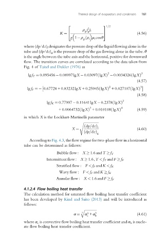

                                     2                 3 1=2
                                               2
                                            ρ j j l
                                              g g
                                K ¼  4                 5                 (4.56)
                                      g 1 ρ =ρ μ cosθ
                                             g
                                                l
                                                   l
              where (dp/dz) l designates the pressure drop of the liquid flowing alone in the
              tube and (dp/dz) g is the pressure drop of the gas flowing alone in the tube. θ
              is the angle between the tube axis and the horizontal, positive for downward
              flow. The transition curves are correlated according to the data taken from
              Fig. 4 of Taitel and Dukler (1976) as

                                                          2                3
                                                    ð
                lg f T ¼ 0:095456 0:08997lgX  0:03097 lgXÞ  0:0034326 lgXÞ
                                                                      ð
                                                                         (4.57)

                                                          2                3
                                                                     ð
               lg f F ¼  0:67728 + 0:83232lgX +0:25945 lgXð  Þ +0:027107 lgXÞ
                                                                         (4.58)
                                                                 2
                          lg f K ¼ 0:77997 0:11641lgX  0:2378 lgXð  Þ
                                                3                4
                                                           ð
                                           ð
                                +0:0064732 lgXÞ +0:010108 lgXÞ           (4.59)
              in which X is the Lockhart-Martinelli parameter
                                           s ffiffiffiffiffiffiffiffiffiffiffiffiffiffiffiffiffiffi
                                             ð dp=dzÞ l
                                       X ¼                               (4.60)
                                             ð dp=dzÞ
                                                    g
                 According to Fig. 4.3, the flow regime for two-phase flow in a horizontal
              tube can be determined as follows:

                               Bubble flow : X   1:6 andT   f T
                          Intermittent flow : X   1:6,T < f T and F   f F
                               Stratified flow : F < f F andK < f K
                                Wavy flow : F < f F andK   f K
                               Annular flow : X < 1:6and F   f F

              4.1.2.4 Flow boiling heat transfer
              The calculation method for saturated flow boiling heat transfer coefficient
              has been developed by Kind and Saito (2013) and will be introduced as
              follows:

                                           q  ffiffiffiffiffiffiffiffiffiffiffiffiffiffi
                                            3  3   3
                                        α ¼   α + α                      (4.61)
                                               c   b
              where α c is convective flow boiling heat transfer coefficient and α b is nucle-
              ate flow boiling heat transfer coefficient.
   168   169   170   171   172   173   174   175   176   177   178