Page 174 - Design and Operation of Heat Exchangers and their Networks
P. 174

162   Design and operation of heat exchangers and their networks


                 10                                               10 4
                           Annular
                                      X =1.6        Bubble
                  1             f                                 10 3
                                                   f
                                 F
                                                    T
               T,F  10 −1                                         10 2  K
                            Wavy                  Intermittent
                                                  (plug/slug)
                10 −2                                             10
                               f K
                                  Stratified
                10 −3  −3  −2    −1                  2      3     4 1
                   10   10     10      1     10    10     10    10
                                         X
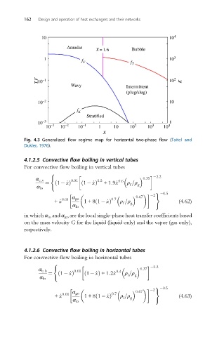
          Fig. 4.3 Generalized flow regime map for horizontal two-phase flow (Taitel and
          Dukler, 1976).


          4.1.2.5 Convective flow boiling in vertical tubes
          For convective flow boiling in vertical tubes
                    (
                                                              2:2
                                                         0:35
               α c,v        0:01      1:5      0:6
                  ¼ ð  1  _xÞ   ð 1  _xÞ  +1:9_x  ρ =ρ g
                                                   f
               α lo
                                                             )  0:5
                                                            2
                                                      0:67
                             α go
                      + _x 0:01  1+8 1  _xÞ 0:7  ρ =ρ                 (4.62)
                                      ð
                                                f  g
                             α lo
          in which α lo and α go are the local single-phase heat transfer coefficients based
          on the mass velocity G for the liquid (liquid only) and the vapor (gas only),
          respectively.
          4.1.2.6 Convective flow boiling in horizontal tubes
          For convective flow boiling in horizontal tubes

                      (
                                                             2:2
                                                        0:37
                α c,h         0:01            0:4
                    ¼ ð 1  _xÞ   ð 1  _xÞ +1:2_x  ρ =ρ g
                                                  l
                α lo
                                                             )  0:5
                                                            2
                                                      0:67
                             α go
                      + _x 0:01  1+8 1  _xÞ 0:7  ρ =ρ                 (4.63)
                                      ð
                                                l  g
                             α lo
   169   170   171   172   173   174   175   176   177   178   179