
Page 214 - Design and Operation of Heat Exchangers and their Networks
P. 214
Optimal design of heat exchangers 203
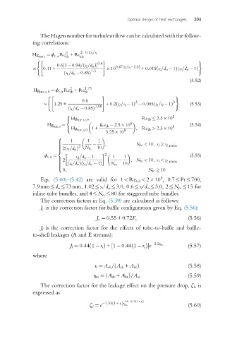
The Hagen number for turbulent flow can be calculated with the follow-
ing correlations:
2
Hg ¼ ϕ Re +Re 2 0:1s l =s t
tur,i t,n tb tb
( " # )
0:6
ð
½
0:61 0:94= s l =d o Þ 0:47 s l =s t 1:5Þ
ð
ð
ð
0:11 + 10 +0:015 s t =d o 1Þ s l =d o 1Þ
1:3
ð s t =d o 0:85Þ
(5.52)
2
Hg tur,s,0 ¼ ϕ t,n Re +Re 1:75
tb
tb
( " # )
0:6 3 3
1:25 + 1:08 +0:2 s l =s t 1ð Þ 0:005 s t =s l 1Þ (5.53)
ð
ð s t =d o 0:85Þ
8 5
Hg , Re tb 2:5 10
< tur,s,0
5
Hg ¼ Re tb 2:5 10 (5.54)
tur,s 5
: Hg tur,s,0 1+ 5 ,Re tb > 2:5 10
3:25 10
8
1 1 1
>
> , N rc < 10, s l s
> l, min
> 2
> N rc 10
ð
> 2 s t =d o Þ
<
2
ϕ t,n ¼ s d =d o 1 1 1 (5.55)
> 2 , N rc < 10, s l < s
> l, min
>
> ð s t =d o Þ s t =d o 1ð Þ N rc 10
>
>
:
0, N rc 10
6
Eqs. (5.40)–(5.42) are valid for 1<Re t,d <2 10 , 0.7 Pr 700,
7.9mm d o 73mm, 1.02 s t /d o 3.0, 0.6 s l /d o 3.0, 2 N rc 15 for
inline tube bundles, and 4 N rc 80 for staggered tube bundles.
The correction factors in Eq. (5.39) are calculated as follows:
J c is the correction factor for baffle configuration given by Eq. (5.56):
J c ¼ 0:55 + 0:72F c (5.56)
J l is the correction factor for the effects of tube-to-baffle and baffle-
to-shell leakages (A and E streams):
ð
J l ¼ 0:44 1 r s Þ +1 0:44 1 r s Þ½ ð e 2:2r lm (5.57)
where
ð
r s ¼ A sb = A sb + A bt Þ (5.58)
ð
r lm ¼ A sb + A bt Þ=A sc (5.59)
The correction factor for the leakage effect on the pressure drop, ζ l ,is
expressed as
ð
0:8 0:15 1 + r s Þ
1:33 1 + r s Þr
ζ ¼ e ð lm (5.60)
l