
Page 260 - Design and Operation of Heat Exchangers and their Networks
P. 260
Optimal design of heat exchanger networks 249
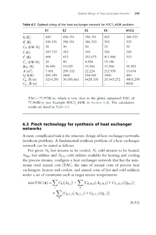
Table 6.2 Optimal sizing of the heat exchanger network for H2C2_443K problem.
E1 E2 E3 E4 H1CU
0
t h (K) 443 436.151 356.151 423 346.333
00
t h (K) 436.151 356.151 346.333 303 333
_
C h (kW/K) 30 30 30 15 30
0
t c (K) 397.727 353 293 293 293
t c (K) 408 413 353.675 411.846 313
00
_
C c (kW/K) 20 40 4.854 15.146 –
Δt m (K) 36.686 10.029 16.566 10.566 36.565
2
A (m ) 7.001 299.132 22.224 212.939 13.674
Q (kW) 205.459 2400 294.541 1800 400
C E ($/yr) 3214.281 30,585.663 6428.335 24,943.272 4803.299
C U ($/yr) – – – – 8000
TAC¼77,975$/yr, which is very close to the global optimized TAC of
77,964$/yr (see Example H2C2_443K in Section 6.4). The calculation
results are listed in Table 6.2.
6.3 Pinch technology for synthesis of heat exchanger
networks
A more complicated task is the structure design of heat exchanger networks
(synthesis problem). A fundamental synthesis problem of a heat exchanger
network can be stated as follows.
For given N h hot streams to be cooled, N c cold streams to be heated,
N HU hot utilities and N CU cold utilities available for heating and cooling
the process streams, configure a heat exchanger network that has the min-
imum total annual cost (TAC, the sum of annual costs of process heat
exchangers, heaters and coolers, and annual costs of hot and cold utilities)
under a set of constraints such as target stream temperatures:
X X
ð
minTAC xðÞ ¼ C E A E, j + ½ C E,H,k A E,H,k Þ + C U,H,k Q H,k Þ
ð
j k
X
+ ½ C E,C,l A E,C,l Þ + C E,C,l Q C,l Þ
ð
ð
k
(6.53)