Page 270 - Design and Operation of Heat Exchangers and their Networks
P. 270

258   Design and operation of heat exchangers and their networks


                          45°C       125°C   125°C     175°C
                     H1                                       H1
                         (10 kW/K)                    (10 kW/K)
                          65°C       125°C
                     H2  (40 kW/K)           H2
                          20°C       120°C   120°C     155°C
                     C1                                       C1
                          (20 kW/K)                    (20 kW/K)
                          40°C       112°C
                     C2
                          (15 kW/K)
                          Cold end part  Pinch     Hot end part
                         (below the pinch)       (above the pinch)
          Fig. 6.4 Pinch decomposition of Example 6.4 (H2C2_175R), Δt m ¼5K.

                                          _
                                    _
             temperature intervals. Since C H1 < C C1 , according to Eq. (6.77), a splitting
             in C1 with a new match H2C1 and a corresponding splitting in H2 is
             necessary. Furthermore, as has been analyzed in the aforementioned
             problem table, the minimum cooling duty for hot stream H1 is 120kW,
             and the minimum heating duty for cold stream C1 is 200kW; therefore,
             a cooler is added to hot stream H1, and a heater is added to cold stream
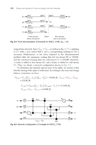
             C1. Thus, we obtain a network configuration shown in Fig. 6.5.
                To determine the thermal capacity rates of the splits, we assume at first
             that the mixing of the splits is isothermal. According to the mass and energy
             balance constraints, we have
                                                       _

                                                             _
                      _
               _
                                                                   _
                                 = t
              C h,E4 ¼ C c,2 t 00 c,2   t 0 c,2       0 h,2   t 00 h,2    ¼ 18kW=K, C h,E3 ¼ C h,2  C h,E4
                   ¼ 22 kW=K
                     _
                           _

                                 0
                                        = t c,pinch  t
                    C c,E3 ¼ C h,E,3 t h,2   t 00 h,2       0 c,1   ¼ 13:2kW=K,
                           _
                                 _
                     _
                    C c,E2 ¼ C c,1  C c,E3 ¼ 6:8kW=K
                              E1  t     E2
                      175         pinch                       45
                H1
                      (10)
                                              E3
                      123                                     65
                H2
                      (40)
                      155                                     20
                                                              (20)  C1
                      112                                     40   C2
                                     – Dt                     (15)
                                 t pinch  m        E4
          Fig. 6.5 Network configuration of Example 6.4 (H2C2_175R).
   265   266   267   268   269   270   271   272   273   274   275