Page 321 - Design and Operation of Heat Exchangers and their Networks
P. 321

Optimal design of heat exchanger networks  307


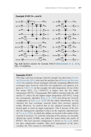
                Example H10C10—cont’d

                          1100                                3150
                     220     (10.61347)  120            180           75
                H5                                 H1
                     (25)                               (30)
                                                           1050
                                  2050  800
                     280                  90            190           50
                H9   (15)                                             (30)  C4
                                                              3150
                     150                  40            180           75
                                              C6   H3
                                         (10)           (30)
                     150                  40  C7        130           40  C9
                                         (20)                         (35)
                              1400                                1050
                       1100
                     210                 120  C8        140   1800    45
                                         (35)      H4   (30)
                          2400
                     280                 120            120           60
                H2                                                        C10
                     (15)                                             (30)
                                      744                         1503
                             1456.201                      2246.502
                     180                  60            170           45
               H10                                 H7
                     (30)                               (30)
                                                           1753
                     230                  40  C1        250           50  C5
                                         (20)                         (20)
                       3444       1400
                     260                 120           180    3900    50
                                         (35)  C2  H8   (30)
                                      1250                1350
                     180                  55           190            40
                H6                                                        C3
                      (10)                                            (35)
               Fig. 6.33 Optimal solution for Example H10C10 (Bohnenstaedt et al., 2014),
               TAC¼1,716,695$/yr.
                 Example H13C7
                 This large-scale heat exchanger network example was taken from Escobar
                 and Trierweiler (2013) who used the problem data of Sorsak and Kravanja
                 (2002) for synthesis of heat exchanger networks comprising different heat
                 exchanger types, however, with their own equipment cost equation, as is
                 given in Table 6.34. In this example, the inlet temperature of one of the
                 hot stream (H13, T out ¼1034.5°C) is higher than the hot utility
                 temperature (927°C). Consequently, H13 shall be matched with the cold
                 stream C7, which has the highest target temperature (923.78°C). Using
                 the monogenetic algorithm (Fieg et al., 2009) and taking the network
                 configuration of Xiao et al. (2018) for the initial subnetworks, we had
                 obtained the heat exchanger network better than previous optimal
                 results. However, we noticed that in the obtained network, H13 is
                 heated again to reach its target temperature. This is because of the fact
                 that the monogenetic algorithm is based on the stagewise superstructure
                 of Yee et al. (1990), in which the utilities are located at the outlets of the
                 network if necessary. To avoid the reheating of hot streams, we manually
                 deleted the match H13HU and added the heater before the match of
                 H13C7. The best network configuration is shown in Fig. 6.34, which
                 has three independent variables. After local optimization of the three
                 variables, the TAC reaches to 1,410,649$/yr.
                                                                        Continued
   316   317   318   319   320   321   322   323   324   325   326