
Page 319 - Design and Operation of Heat Exchangers and their Networks
P. 319
Optimal design of heat exchanger networks 305
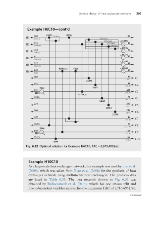
Example H6C10—cont’d
385 12857 (78.5403) 12270 159
H1
(131.51) (186.0371)
(402.1666) 324812
516 (273.3042) 43
H2
(1198.96) (149.7297)
18926
132 82
H3
(378.52)
18276
91 60
H4
(589.549)
32402
217 43
H5
(186.216)
43986.12 7469 18840
649 43
H6
(116)
385 30 C1
(119.1)
42281
471 99
(191.05) C2
7033 71071
521 437 C3
HU1 (377.91)
24711.93
418.6 78
(160.43) C4
54642
234 217 C5
(1297.7)
22061
266 256
(2753) C6
27530
149 49
(197.39) C7
163.4 59 C8
(123.156)
2660
649 163
HU1 (95.98) C9
221.3 219 C10
(1997.5)
4594
Fig. 6.32 Optimal solution for Example H6C10, TAC¼6,673,406$/yr.
Example H10C10
As a large-scale heat exchanger network, this example was used by Luo et al.
(2009), which was taken from Xiao et al. (2006) for the synthesis of heat
exchanger network using multistream heat exchangers. The problem data
are listed in Table 6.33. The best network shown in Fig. 6.33 was
obtained by Bohnenstaedt et al. (2014), which has one stream split and
five independent variables and reaches the minimum TAC of 1,716,695$/yr.
Continued