
Page 44 - Design and Operation of Heat Exchangers and their Networks
P. 44
Basic thermal design theory for heat exchangers 31
Here, we should pay attention to kA, in which k is always related to its
corresponding heat transfer area A. For example, if A is the outside area of a
tube, then we should definitively express that k is based on the tube outside
area. If k is based on the area of tube inside, A must be the tube inner area.
The third term of the right side of Eq. (2.61) represents the thermal
resistance of the wall, in which A m is the mean wall area perpendicular to
conductive heat flux through the wall. For a tube wall,
2πδ w L
A m ¼ (2.62)
ð
ln d o =d i Þ
The conductive thermal resistance per unit area of tube inside can be
expressed as
ð
δ w d i ln d o =d i Þ
R w,i ¼ ¼ (2.63)
λ w A m = πd i LÞ 2λ w
ð
For the heat exchangers with extended heat transfer surfaces (finned sur-
faces), Eq. (2.61) should be rewritten as
1 1 R f,h δ w R f ,c 1
¼ + + + + (2.64)
α
kA η 0,h h A h η 0,h A h λ w A m η A c η α c A c
0,c
0,c
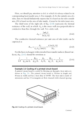
Example 2.3 Cooling of a printed circuit board
A printed circuit board is cooled by blowing air through a heat sink as is
shown in Fig. 2.6. The printed circuit board is 150mm in length and
80mm in width and has a heat duty of 100W. The heat sink is made of
aluminum and has 13 rectangular air flow channels with channel spacing
d
h fs
s fs d f
d
L
B
Fig. 2.6 Cooling of a printed circuit board.
Continued