
Page 49 - Design and Operation of Heat Exchangers and their Networks
P. 49
36 Design and operation of heat exchangers and their networks
t² c
t¢ h t² h
.
C h
t¢ h .
Dt C c t¢ c
t c ² q
t² h
t¢ c
z
(A) 0 L
.
t¢ c C c
t¢ h t² h
.
C h
¢
t h
Dt t² c
t²
q h
t² c
¢
t c
z
(B) 0 L
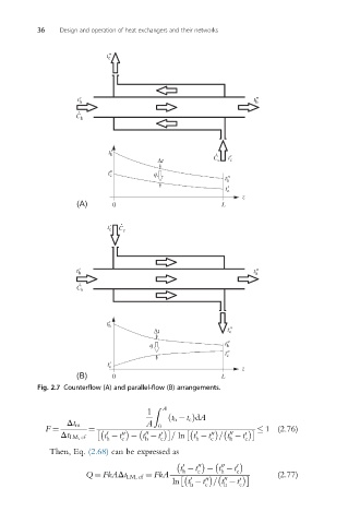
Fig. 2.7 Counterflow (A) and parallel-flow (B) arrangements.
Z A
1
ð t h t c ÞdA
A
Δt m 0
F ¼ ¼ 1 (2.76)
0
00
00
0
00
Δt LM, cf t t 00 t t 0 = ln t t = t t 0
h c h c h c h c
Then, Eq. (2.68) can be expressed as
00
0
t t 00 c t t 0 c
h
h
Q ¼ FkAΔt LM, cf ¼ FkA (2.77)
0
ln t t = t t 0
00
00
h c h c