
Page 53 - Design and Operation of Heat Exchangers and their Networks
P. 53
40 Design and operation of heat exchangers and their networks
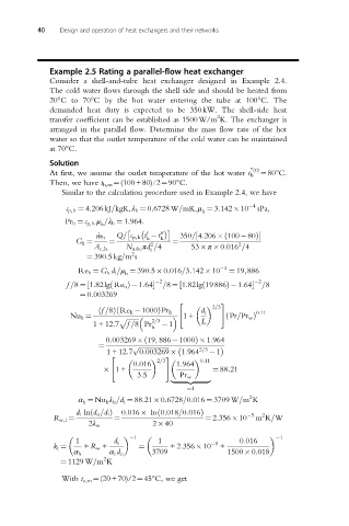
Example 2.5 Rating a parallel-flow heat exchanger
Consider a shell-and-tube heat exchanger designed in Example 2.4.
The cold water flows through the shell side and should be heated from
20°Cto70°C by the hot water entering the tube at 100°C. The
demanded heat duty is expected to be 350kW. The shell-side heat
2
transfer coefficient can be established as 1500W/m K. The exchanger is
arranged in the parallel flow. Determine the mass flow rate of the hot
water so that the outlet temperature of the cold water can be maintained
at 70°C.
Solution
00 (0)
At first, we assume the outlet temperature of the hot water t h ¼80°C.
Then, we have t h,m ¼(100+80)/2¼90°C.
Similar to the calculation procedure used in Example 2.4, we have
c p,h ¼ 4:206kJ=kgK,λ h ¼ 0:6728 W=mK,μ ¼ 3:142 10 4 sPa,
h
Pr h ¼ c p,h μ =λ h ¼ 1:964:
h
Q= c p,h t t 00
0
ð
½
_ m h h h 350= 4:206 100 80Þ
G h ¼ ¼ 2 ¼ 2
A c,h N tube πd =4 53 π 0:016 =4
i
2
¼ 390:5kg=m s
Re h ¼ G h d i =μ ¼ 390:5 0:016=3:142 10 4 ¼ 19;886
h
2 2
ð
f =8 ¼ 1:82lg Re h Þ 1:64½ ð =8 ¼ 1:82lg 19 886Þ 1:64 =8
½
¼ 0:003269
" #
2=3
ð
ð f =8Þ Re h 1000ÞPr h d i 0:11
Nu h ¼ 1+ ð Pr=Pr w Þ
p ffiffiffiffiffiffiffi 2=3
1+12:7 f =8 Pr 1 L
h
0:003269 19, 886 1000Þ 1:964
ð
¼ p ffiffiffiffiffiffiffiffiffiffiffiffiffiffiffiffiffiffi
1+ 12:7 0:003269 1:964 2=3 1
" #
2=3 0:11
0:016 1:964
1+ ¼ 88:21
3:5 Pr w
|fflfflfflfflfflfflfflffl{zfflfflfflfflfflfflfflffl}
¼1
2
α h ¼ Nu h λ h =d i ¼ 88:21 0:6728=0:016 ¼ 3709 W=m K
ð
d i ln d o =d i Þ 0:016 ln 0:018=0:016Þ 5 2
ð
R w,i ¼ ¼ ¼ 2:356 10 m K=W
2λ w 2 40
1 1
1 d i 1 5 0:016
k i ¼ + R w + ¼ +2:356 10 +
α h α c d o 3709 1500 0:018
2
¼ 1129 W=m K
With t c,m ¼(20+70)/2¼45°C, we get