
Page 444 - Design and Operation of Heat Exchangers and their Networks
P. 444
426 Design and operation of heat exchangers and their networks
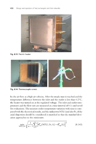
Fig. 8.13 Electric heater.
Fig. 8.14 Thermocouple screen.
by the air flow at a high air velocity. After the steady state is reached and the
temperature difference between the inlet and the outlet is less than 0.2°C,
the heater was turned on at the regulated voltage. The inlet and outlet tem-
peratures and the flow rate are measured at a time interval of 0.1s and saved
for evaluations. The measure outlet temperature variation with time is com-
pared with the theoretical results, and the unknown NTU (and also Pe, if the
axial dispersion should be considered) is matched so that the standard devi-
ation approaches to the minimum:
s ffiffiffiffiffiffiffiffiffiffiffiffiffiffiffiffiffiffiffiffiffiffiffiffiffiffiffiffiffiffiffiffiffiffiffiffiffiffiffiffiffiffiffiffiffiffiffiffiffiffiffiffiffiffiffiffiffiffiffiffiffiffiffiffiffiffiffiffiffiffiffiffiffiffiffiffiffi
n
1 X h i 2
min θ ð NTU, Pe, τ i Þ θ 00 τ i ðÞ (8.143)
00
NTU,Pe n 1 cal exp
i¼1