
Page 440 - Design and Operation of Heat Exchangers and their Networks
P. 440
Experimental methods for thermal performance of heat exchangers 423
Substituting Eqs. (8.132), (8.137), (8.138) into Eq. (8.131) and solving
Eqs. (8.131), (8.133), we obtain the solution in the Laplace domain as
sNTU
0 x sBx
e
e Þ ¼ ϕ x, sÞθ sðÞe s + NTU e (8.141)
θ x, sð ð
The complex coefficient φ represents the effect of the fin dynamics on the
dynamic response of the fluid:
( 2 )
2
s 1 η Þ ξ ζÞ NTU 2
ð
ð
f
ϕ ¼ exp x
ð
ð
ð s + NTUÞ sζ + ξNTUÞ s + NTU 1 η Þ sζ + ξNTUÞ
ð
½
f
(8.142)
If ξ¼ζ, the fin dynamics is the same as the wall dynamics; therefore, there is
no heat conduction along the fin height. In this case, the fins and the wall can
be treated as one porous medium, and the traditional model can be used.
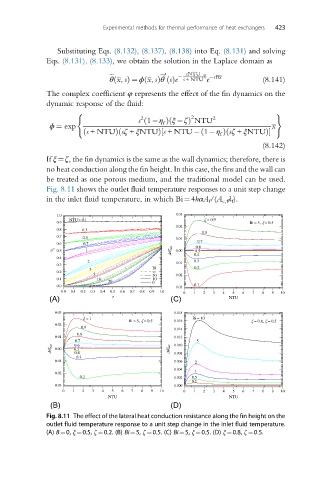
Fig. 8.11 shows the outlet fluid temperature responses to a unit step change
in the inlet fluid temperature, in which Bi¼4hαA f /(A c,f λ f ).
1.0 0.03
NTU= 0.1 = 0.9
0.9 Bi = 5, = 0.5
0.02
0.8 0.3
0.8
0.7 0.5 0.01
0.6 0.7 0.7
" 0.5 1 " max 0.00 0.6
0.5
0.4
0.4
2 0.3
0.3 0.01
3 Bi 0.2
0.2
5 50 0.02
0.1 10 10
20 0
0.0 0.03 0.1
0.0 0.1 0.2 0.3 0.4 0.5 0.6 0.7 0.8 0.9 1.0 0 1 2 3 4 5 6 7 8 9 10
(A) (C) NTU
0.03 0.018
= 1 Bi = 10
Bi = 5, = 0.5 0.016 = 0.8, = 0.5
0.02
0.9
0.014
0.8
0.01 0.012
0.7 5
" max 0.00 0.6 " max 0.010
0.5
0.4 0.008
0.3
0.01 0.006 2
0.004 1
0.02
0.2 0.002 0.5
0.2
0.03 0.000
0 1 2 3 4 5 6 7 8 9 10 0 1 2 3 4 5 6 7 8 9 10
NTU NTU
(B) (D)
Fig. 8.11 The effect of the lateral heat conduction resistance along the fin height on the
outlet fluid temperature response to a unit step change in the inlet fluid temperature.
(A) B¼0, ξ¼0.5, ζ ¼0.2. (B) Bi¼5, ζ¼0.5. (C) Bi¼5, ξ¼0.5. (D) ξ¼0.8, ζ¼0.5.