
Page 437 - Design and Operation of Heat Exchangers and their Networks
P. 437
420 Design and operation of heat exchangers and their networks
1.0
NTU = 0.1
0.9
0.8 0.3
0.7
0.5
0.6 0.7
q 0.5 1
0.4
0.3 2
3 K w
0.2 0.1
5
0.1 10 0.05
20 0
0.0
0.0 0.1 0.2 0.3 0.4 0.5 0.6 0.7 0.8 0.9 1.0
t
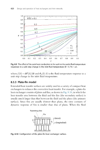
Fig. 8.9 The effect of the axial heat conduction in the wall on the outlet fluid temperature
responses to a unit step change in the inlet fluid temperature (B¼0, Pe¼∞).
0
where f τðÞ ¼ dθ τðÞ=dτ and θ U x, τÞ is the fluid temperature response to a
ð
unit step change in the inlet fluid temperature.
8.3.3 Plate-fin model
Extended heat transfer surfaces are widely used in a variety of compact heat
exchangers to enhance the convective heat transfer. For example, a plate-fin
heat exchanger consists of plates and fins, as shown in Fig. 8.10, in which the
heat transfer area between the fluid and the fins (the secondary surface) is
usually much larger than that between the fluid and the plates (the primary
surface). Since fins are usually thinner than plates, the time constant of
dynamic response of fins is smaller than that of plates. When the fluid
Fig. 8.10 Configuration of the plate-fin heat exchanger surface.