
Page 436 - Design and Operation of Heat Exchangers and their Networks
P. 436
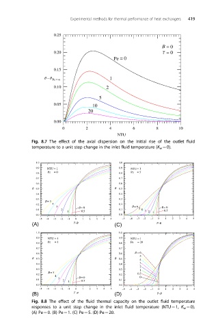
Experimental methods for thermal performance of heat exchangers  419


                      0.25

                                                                 B = 0
                      0.20                                       −
                                                                 τ = 0
                                              Pe = 0

                      0.15
                  θ− θ Pe = ∞               1
                      0.10                 2

                                        5
                      0.05            10
                                    20

                      0.00
                          0        2        4         6        8        10
                                               NTU
              Fig. 8.7 The effect of the axial dispersion on the initial rise of the outlet fluid
              temperature to a unit step change in the inlet fluid temperature (K w ¼0).


               1.0                              1.0
               0.9  NTU = 1                     0.9  NTU= 1
               0.8  Pe  = 0                     0.8  Pe  = 5
               0.7                              0.7
               0.6                              0.6
              q  0.5                          q  0.5
               0.4                              0.4
               0.3                              0.3
                   B= 5
               0.2    4                         0.2
                       3        B= 0                 B= 6        B= 0
               0.1       2                      0.1     5  4  3   0.5
                            1    0.5                        2 1
               0.0                              0.0
                 –5  –4  –3  –2  –1  0  1  2  3  4  5  –5  –4  –3  –2  –1  0  1  2  3  4  5
              (A)             t –B            (C)              t –B
               1.0                              1.0
               0.9  NTU = 1                     0.9  NTU = 1
               0.8  Pe  = 1                     0.8  Pe  = 20
               0.7                              0.7
               0.6                              0.6   B = 6
                                                        5
              q  0.5                          q  0.5    4
               0.4                              0.4     3
                                                        2
               0.3                              0.3     1
                    B = 5
               0.2                              0.2    0.5
                       4
                        3       B= 0                    0
               0.1        2  1   0.5            0.1
               0.0                              0.0
                 –5  –4  –3  –2  –1  0  1  2  3  4  5  –5  –4  –3  –2  –1  0  1  2  3  4  5
              (B)             t –B            (D)              t –B
              Fig. 8.8 The effect of the fluid thermal capacity on the outlet fluid temperature
              responses to a unit step change in the inlet fluid temperature (NTU¼1, K w ¼0).
              (A) Pe¼0. (B) Pe¼1. (C) Pe¼5. (D) Pe¼20.