
Page 435 - Design and Operation of Heat Exchangers and their Networks
P. 435
418 Design and operation of heat exchangers and their networks
1.0 1.0
0.9 0.9
0.8 0.8
0.7 Pe = 0 0.7
0.6 1 0.6
2 Pe = 0
θ 0.5 5 θ 0.5 1
0.4 20 0.4 2
∞ 5
0.3 0.3 20
B = 0 ∞ B = 0
0.2 0.2
NTU = 0.5 NTU = 2
0.1 0.1
0.0 0.0
0 1 2 3 4 5 0 1 2 3 4 5
(A) τ − (C) − τ
1.0 1.0
0.9 0.9
0.8 0.8
0.7 0.7
0.6 0.6
Pe = 0 Pe = 0
θ 0.5 1 θ 0.5 1
0.4 2 0.4 2
5 5
0.3 20 0.3 20
0.2 ∞ NTU B = 0 0.2 ∞ NTU B = 0
= 1
= 10
0.1 0.1
0.0 0.0
0 1 2 3 4 5 0 1 2 − 3 4 5
(B) τ − (D) τ
1.0
NTU= 0.1
0.9
0.8 0.3
0.7 0.5
0.6 0.7
θ 0.5 1
0.4
2
0.3
Pe
3
0.2 10
5
0.1 10 20
20 ∞
0.0
0.0 0.1 0.2 0.3 0.4 0.5 0.6 0.7 0.8 0.9 1.0
−
τ
(E)
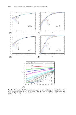
Fig. 8.6 The outlet fluid temperature responses to a unit step change in the inlet
fluid temperature (B¼0, K w ¼0). (A) NTU¼0.5. (B) NTU¼1. (C) NTU¼2. (D) NTU¼10.
(E) NTU ¼ 0.1 20.