
Page 452 - Design and Operation of Heat Exchangers and their Networks
P. 452
Optimal control process of heat exchanger networks 435
00
t t 00 0 (9.7)
i ub,i
000
t 00 t 0 (9.8)
lb,i i
00
000
t t ub,i 0 (9.9)
i
00
00
where t ub,i and t lb,i are upper and lower bound target temperatures of the ith
fluid. Then, we can regulate the flow rate of the heating medium or the
bypass of the working fluid to maintain the fluid temperature within
the target temperature range. Similarly, for the case using a cooler at the
ith exit of the network, the following constraints should be met:
00
t 00 t 0 (9.10)
lb,i i
000
t 00 t 0 (9.11)
lb,i i
000
t t 00 0 (9.12)
i ub,i
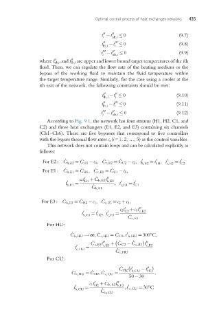
According to Fig. 9.1, the network has four streams (H1, H2, C1, and
C2) and three heat exchangers (E1, E2, and E3) containing six channels
(Ch1–Ch6). There are five bypasses that correspond to five controllers
with the bypass thermal flow rates c i (i=1, 2, …, 5) as the control variables.
This network does not contain loops and can be calculated explicitly as
follows:
_
_
_
_
0
For E2 : C h,E2 ¼ C H1 c 4 , C c,E2 ¼ C C2 c 2 , t 0 ¼ t , t 0 ¼ t 0
h,E2 H1 c,E2 C2
_
_
_
_
For E1 : C h,E1 ¼ C H1 , C c,E1 ¼ C C1 c 5 ,
_
c 4 t 0 H1 þC h,E2 t h,E2
00
t 0 h,E1 ¼ , t 0 c,E1 ¼ t 0 C1
_
C h,E1
_
_
For E3 : C h,E3 ¼ _ C H2 c 1 , C c,E3 ¼ c 2 þc 3 ,
0
c 2 t C2 þc 3 t 00 c,E2
0
0
0
t h,E3 ¼ t , t c,E3 ¼
_
H2
C c,E3
For HU:
_
_
_
0
C h,HU ! ∞,C c,HU ¼ C C2 ,t h,HU ¼ 300°C,
_
_
_
00
C c,E3 t 00 c,E3 þ C C2 C c,E3 t c,E2
t 0 ¼
c,HU _
C c,HU
For CU:
_
C H2 t 0 t 00
_ _ _ h,CU H2
C h,HU ¼ C H2 ,C c,CU ¼ ,
50 30
_
00
0
c 1 t H2 þC h,E3 t h,E3
0
t 0 ¼ ,t c,CU ¼ 30°C
h,CU _
C h,CU