Page 451 - Design and Operation of Heat Exchangers and their Networks
P. 451

434   Design and operation of heat exchangers and their networks


             is 171.428 10  4  $/kWh, and the cold utility cost (30–50°C) is
             60.576 10  4  $/kWh. All heat exchangers including the heater and cooler
             are of counterflow type. For the variation range of operation conditions
             given in Table 9.1, determine the flexibility index and flexibility factor.
             Solution
                 00
             Let t i be the temperature of the ith fluid at the exit of the network before
                                        000
             entering a heater or cooler, and t i be that at the exit of the network after
             leaving a heater or cooler. If there is no heater or cooler at the network
                                     000  00
             exit of the ith fluid, we have t i =t i .
                For the case using a heater at the ith exit of the network, it requires
                Table 9.1 Nominal operation conditions and deviations of Example 9.1.
                              _
                Stream        C (kW/K)       t (°C)        t (°C)
                                                            00
                                             0
                H1            1.4 0.4        310 10         50
                H2            2.0            450            280
                C1            3.0            40             120
                C2            2.0 0.4        115 5          280


                                          c
                    H2         2           1          2   H2
                       CU                Ch1
                                         Ch2                 HU
                                 c 2
                                          E3
                         C2   4                       4        C2
                                         c 3
                                         Ch3
                                         Ch4
                                          E2
                         H1    1                      1   H1
                                                   c 4
                                         Ch5
                                         Ch6
                                          E1
                         C1   3                       3   C1
                                          c 5
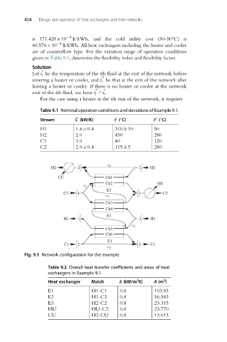
          Fig. 9.1 Network configuration for the example.

                   Table 9.2 Overall heat transfer coefficients and areas of heat
                   exchangers in Example 9.1.
                                                     2
                                                               2
                   Heat exchanger   Match     k (kW/m K)    A (m )
                   E1               H1-C1      0.8          103.83
                   E2               H1-C2      0.8          56.583
                   E3               H2-C2      0.8          23.315
                   HU               HU-C2      0.8          23.770
                   CU               H2-CU      0.8          13.013
   446   447   448   449   450   451   452   453   454   455   456