Page 453 - Design and Operation of Heat Exchangers and their Networks
P. 453
436   Design and operation of heat exchangers and their networks


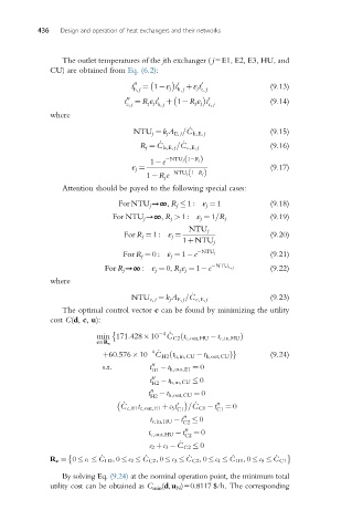
                The outlet temperatures of the jth exchanger ( j=E1, E2, E3, HU, and
             CU) are obtained from Eq. (6.2):

                                 t 00  ¼ 1 ε j t  0  þε j t 0      (9.13)
                                  h, j      h, j  c, j

                               t 00 c, j  ¼ R j ε j t 0 h, j  þ 1 R j ε j t 0 c, j  (9.14)
             where
                                               _
                                  NTU j ¼ k j A E, j =C h,E, j     (9.15)
                                        _     _
                                   R j ¼ C h,E, j =C c,E, j        (9.16)
                                              ð
                                      1 e  NTU j 1 R jÞ
                                 ε j ¼                             (9.17)
                                               ð
                                     1 R j e  NTU j 1 R jÞ
                Attention should be payed to the following special cases:
                              For NTU j →∞, R j   1 : ε j ¼ 1      (9.18)
                             For NTU j →∞, R j > 1 : ε j ¼ 1=R j   (9.19)
                                               NTU j
                               For R j ¼ 1 : ε j ¼                 (9.20)
                                              1þNTU j
                               For R j ¼ 0 : ε j ¼ 1 e  NTU j      (9.21)
                           For R j →∞ : ε j ¼ 0, R j ε j ¼ 1 e  NTU c, j  (9.22)
             where
                                                _
                                 NTU c, j ¼ k j A E, j =C c,E, j   (9.23)
                The optimal control vector c can be found by minimizing the utility
             cost C(d, c, u):

                                         4  _
                         min 171:428 10 C C2 t c,out,HU  t c,in,HU Þ
                                             ð
                         c2R c
                                      4  _
                          þ60:576 10 C H2 t h,in,CU  t h,out,CU Þg  (9.24)
                                          ð
                          s:t:        t 00   t h,out,E1 ¼ 0
                                      H1
                                      t 00   t h,in,CU   0
                                      H2
                                     t 00   t h,out,CU ¼ 0
                                      H2
                                 _               _
                              C c,E1 t c,out,E1 þc 5 t 0  =C C1  t  00  ¼ 0
                                            C1        C1
                                      t c,in,HU  t  00    0
                                              C2
                                              00
                                     t c,out,HU  t C2  ¼ 0
                                      c 2 þc 3   _ C C2   0

             R c ¼ 0   c 1   _ C H2 ,0   c 2   _ C C2 ,0   c 3   _ C C2 ,0   c 4   _ C H1 ,0   c 5   _ C C1
                By solving Eq. (9.24) at the nominal operation point, the minimum total
             utility cost can be obtained as C min (d,u N )=0.8117 $/h. The corresponding

