
Page 459 - Design and Operation of Heat Exchangers and their Networks
P. 459
442 Design and operation of heat exchangers and their networks
a k,k¢,s
y k,k¢,s
z
w k,k¢,s x k,k²,k¢,s¢,s k,k¢,s
Stream k b k,s
w k,k²,s¢ x k,k¢,k²,s,s¢ z k,k²,s¢
y k,k²,s¢
a k,k²,s¢
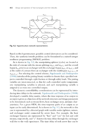
Fig. 9.2 Hyperstructure network representation.
Based on this hyperstructure, possible control alternatives can be considered.
Then, the synthesis/retrofit problem can be formulated as a mixed-integer
nonlinear programming (MINLP) problem.
As is shown in Fig. 9.2, the manipulating splitters (cycles) are located at
the inlet of a stream with the stream splittings w k,k ,s and w k,k ,s and the overall
0
00 0
00 0,and
0
bypass b k,s , prior to an exchanger with the exchanger bypass a k,k ,s or a k,k ,s
at the outlet of a stream from an exchanger with the multibypass x k,k ,k ,s ,s or
00
0 0
x k,k ,k ,s,s For selecting the control scheme, Papalexandri and Pistikopoulos
0.
00
0
(1994b) introduced the pairing binary variables to denote that a specified out-
put is controlled through a split fraction or through utility loads. The pairing
variables are interconnected, so that for each controlled outlet temperature
one manipulating variables is selected, and each manipulating variable is
assigned to at most one controlled output.
The dynamic controllability considerations can be represented by intro-
ducing time delays in the network. Papalexandri and Pistikopoulos (1994b)
developed a variable delay matrix, where the time response of an output to
an input is given as a function of the network structure and design parameters
to be determined, such as stream flows, heat exchanger areas, and pipe char-
acteristics. For a given HEN, the time-response paths of an output to an
input can be easily determined. As is shown in Fig. 9.3, the network in this
case is represented by a directed graph with variable nodes (splitters, mixers,
and exchanger units) connected by arrow lines. For example, the heat
exchanger bypasses are represented by “hex” and “cex” for hot and cold
streams, respectively, and “e” denotes the time delay through the exchanger
wall due to the wall capacitance. The time delay of each arrow line can be