
Page 462 - Design and Operation of Heat Exchangers and their Networks
P. 462
Optimal control process of heat exchanger networks 445
The results of this optimization are then implemented by specifying the opti-
mal value of some variables.
The control objective between different steady states is to regulate other
inlet parameters to maintain the target output parameters of process streams
(usually the output temperatures of the process streams) either exactly at the
nominal operation conditions or as close as possible to the nominal operation
conditions.
According to the degrees of freedom of HEN to achieve the control
objectives, the operation changes of HENs can be divided into three cases:
the number of regulatable parameters is greater than, or equal to, or less than
the number of target output temperatures. If the deviations are within the
feasible region of a HEN, there may exist only one set, or more than one
sets of regulation solutions, to maintain the former target output tempera-
tures. For the case of more than one solutions, the optimal solution should be
determined, which yields an optimization problem.
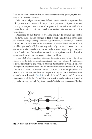
For a HEN, the regulation of stream flow rates is easy to be realized. So
we focus on the tasks for maintaining the stream temperatures. To determine
a needed regulation, the relation between temperature deviations and the
change of inlet parameters should be obtained first, which involves the rating
process of a HEN. To develop the relations to calculate temperature devi-
ations, take a two-stream heat exchanger with bypass control scheme as an
00
0
0
00
example, as is shown in Fig. 9.4, in which t h and t h (or t c and t c) are the
temperatures of the hot (or cold) stream coming to the splitter and leaving
00
00
0
0
from the mixer, t E,h and t E,h (or t E,c and t E,c ) the temperatures of the hot
c C ˙
h h
t¢ h t¢ E,h t² E,h t² h
˙
C h ˙
(1–c h )C h
(1–c )C ˙ c ˙
c
C c
t² c t² E,c t¢ E,c t¢ c
Heat
exchanger ˙
c C c
c
Fig. 9.4 Heat exchanger with bypass control scheme.