Page 95 - Design and Operation of Heat Exchangers and their Networks
P. 95

Steady-state characteristics of heat exchangers  83


              3.2.2.3 Heat exchangers with one fluid having phase change
              In an evaporator or a condenser, one fluid undergoes a phase change during
              which the fluid temperature maintains at its evaporation (or condensation)
              temperature. In such a case, the thermal capacity of the phase-changing fluid
              becomes infinitive large, that is, R¼0. The ε-NTU relation in Eqs. (3.58),
              (3.71) reduces to

                                        ε ¼ 1 e  NTU                     (3.72)

              3.2.2.4 1-2 shell-and-tube heat exchangers
              Nagle (1933) investigated the 1-2, 1-4, 1-6, and 2-4 shell-and-tube heat
              exchangers and derived a series of curves giving the correction factor for
              the logarithmic mean temperature difference. Here, “n-m” means n shell
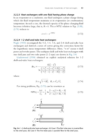
              passes and m tube passes. The multipass shell-and-tube heat exchangers with
              one shell pass and two tube passes (1-2 type) are shown in Fig. 3.4.
                 Underwood (1934) obtained an explicit analytical solution for 1-2
              shell-and-tube heat exchangers:

                                                0
                                             St  t s 00
                                               s
                              Δt m ¼                                     (3.73)
                                           00
                                       t + t  t  t + St  t 00
                                        0
                                               0
                                                  00
                                                        0
                                           s
                                                        s
                                               t
                                                  t
                                       s
                                                           s
                                     ln
                                                        0
                                               0
                                                  00
                                       0
                                       t + t  t  t  St  t   00
                                           00
                                       s   s   t  t     s  s
              where
                                      q ffiffiffiffiffiffiffiffiffiffiffiffiffi
                                             2       _  _
                                  S ¼                                    (3.74)
                                        1+ R , R s ¼ C s =C t
                                             s
                 For sizing problems, Eq. (3.73) can be rewritten as
                                      kA   1   2 ε s 1+ R s  SÞ
                                                    ð
                              NTU s ¼  _  ¼  ln                          (3.75)
                                      C s  S   2 ε s 1+ R s + Sð  Þ

              Fig. 3.4 1-2 shell-and-tube heat exchanger. (A) Case I: The first tube pass is counterflow
              to the shell pass. (B) Case II: The first tube pass is parallel flow to the shell pass.
   90   91   92   93   94   95   96   97   98   99   100