
Page 97 - Design and Operation of Heat Exchangers and their Networks
P. 97
Steady-state characteristics of heat exchangers 85
2
ε s ¼
S 2m NTU s R s NTU s R s R s NTU s
1+ R s + S 2m coth + R s coth coth
2 2 m 2m
(3.82)
where
q ffiffiffiffiffiffiffiffiffiffiffiffiffiffiffiffiffiffiffiffiffiffiffi
2
ð
S 2m ¼ 1+ R s =mÞ (3.83)
We can find that Eq. (3.81) is a special case of Eq. (3.82) for m¼2.
Another equivalent form of the 1-2m exchanger effectiveness can be
found in (Roetzel and Spang, 2010, 2013, Table 4) as
1
1 S 2m R s R s =m
ε s ¼ ð 1+ R s =m S 2m Þ + +
2 1 e S 2m NTU s 1 e R s NTU s 1 e R s NTU s =m
(3.84)
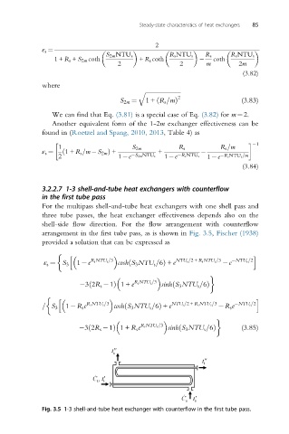
3.2.2.7 1-3 shell-and-tube heat exchangers with counterflow
in the first tube pass
For the multipass shell-and-tube heat exchangers with one shell pass and
three tube passes, the heat exchanger effectiveness depends also on the
shell-side flow direction. For the flow arrangement with counterflow
arrangement in the first tube pass, as is shown in Fig. 3.5, Fischer (1938)
provided a solution that can be expressed as
h i
1 e R s NTU s =3 Þ + e NTU s =2+ R s NTU s =3 e NTU s =2
ε s ¼ S 3 cosh S 3 NTU s =6ð
32R s 1ð Þ 1+ e R s NTU s =3 sinh S 3 NTU s =6ð Þ
h i
1 R s e R s NTU s =3 cosh S 3 NTU s =6Þ + e NTU s =2+ R s NTU s =3 R s e NTU s =2
ð
= S 3
32R s 1ð Þ 1+ R s e R s NTU s =3 sinh S 3 NTU s =6ð Þ (3.85)
Fig. 3.5 1-3 shell-and-tube heat exchanger with counterflow in the first tube pass.