
Page 91 - Design and Operation of Heat Exchangers and their Networks
P. 91
Steady-state characteristics of heat exchangers 79
For the fluids, the change in the heat load can be represented by the
changes in the fluid temperatures:
_
dQ ¼ C h dt h (3.47)
_
dQ ¼ C c dt c (3.48)
where the positive sign in Eq. (3.48) is for the parallel-flow arrangement and
the negative sign is for the counterflow arrangement. Now, we define the
temperature difference between the hot and cold fluids as.
Δt ¼ t h t c (3.49)
_
_
d ΔtÞ ¼ d t h t c Þ ¼ 1=C h 1=C c dQ (3.50)
ð
ð
According to the energy balance, the change in the heat load dQ should
be equal to the heat transferred from the hot fluid to the cold fluid:
dQ ¼ kΔtdA (3.51)
Substitution of Eq. (3.51) into Eq. (3.50) yields
dΔt
_
_
¼ 1=C h 1=C c kdA (3.52)
Δt
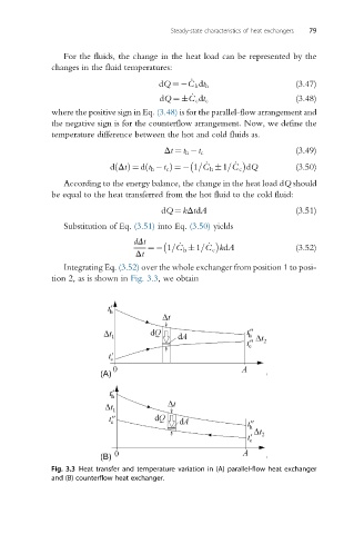
Integrating Eq. (3.52) over the whole exchanger from position 1 to posi-
tion 2, as is shown in Fig. 3.3, we obtain
Fig. 3.3 Heat transfer and temperature variation in (A) parallel-flow heat exchanger
and (B) counterflow heat exchanger.