Page 596 - Design for Six Sigma a Roadmap for Product Development
P. 596
552   Chapter Fifteen


             Example 15.3. Improve a Strain Gauge Strain is the amount of deforma-
             tion of a body due to an applied force. More specifically, strain e is defined as
             the fractional change in length. In most applications, the magnitude of mea-
             sured strain is very small. Therefore, strain is often expressed as microstrain
                               6
              e, which is e
 10 . Strain can be measured by a strain gauge, a device
             whose electrical resistance varies in proportion to the amount of strain in the
             device; this electrical resistance change is usually extremely small in the
             magnitude of microhms (  ). Therefore, the key requirement for strain
             gauge is to measure the small resistance with high degrees of accuracy,
             repeatability, and reproducibility. The output signal is a voltage in the unit
             of millivolts (MV), which should be proportional to the resistance change.
               In this experiment, the signal factor M is the electrical resistance change
             and the functional requirement y is the output voltage. Three levels are sig-
             nal factors, selected as follows: M 1   10   , M 2   100   , and M 3   1000   .
               Certain noise factors, such as environmental temperature, may affect the
             measurement process. Two levels of compounded noise factor, N 1 and N 2 , are
             used in the experiment. Nine control factors, all of them design parameters
             of the strain gauge, are selected in the experiment, and their levels are listed
             in the following table:

                    Control factors     Level 1    Level 2       Level 3
               A  Foil alloy type       Type 1     Type 2
               B Foil thickness         5          10          15
               C Specimen material type  6 nylon   6/6 nylon   6/6 nylon glass
               D Bonding method         Method 1   Method 2    Method 3
               E Outer-grid line width  45/60      40/55       35/40
               F  Inner-grid line width  35        25
               G Coating thickness      9          3
               H End-loop dimension     50         70          80
               I  Specimen thickness    10         25          40

             An L 18 array is used to accommodate control factors. All control factors, the
             noise factor, and the signal factor are assigned to the inner-outer array lay-
             out described in Table 15.3.
               In assigning F and G factors, the compound factor method is used. A com-
             pound factor termed FG is defined as follows:
                       (FG) 1   F 1 G 1 ,  (FG) 2   F 2 G 1 ,  (FG) 3   F 2 G 2
             Because a strain gauge is a measurement system, zero signal–zero output is
                                                       ^
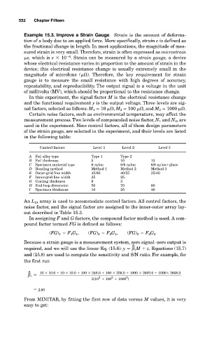
             required, and we will use the linear Eq. (15.6): y   β 1 M   ε. Equations (15.7)
             and (15.8) are used to compute the sensitivity and S/N ratio. For example, for
             the first run

               ^    10
 10.0   10
 10.0   100
 249.0   100
 258.0   1000
 2602.0   1000
 2608.0
               β 1
                                          2
                                               2
                                                     2
                                        2(10   100   1000 )
                   2.60
             From MINITAB, by fitting the first row of data versus M values, it is very
             easy to get:

