
Page 179 - Design of Reinforced Masonry Structures
P. 179
DESIGN OF REINFORCED MASONRY BEAMS 4.43
b b
d t = d d d t
h
Centroid
of bars
x
A s
Bar nearest the tension
face of beam
(a) (b)
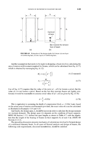
FIGURE 4.8 Estimation of the design depth d of a beam: (a) one layer
of reinforcing bars, (b) two layers of reinforcing bars.
Another assumption that needs to be made in designing a beam involves calculating the
area of tension reinforcement required for flexure, which can be calculated from Eq. (4.77)
which is obtained by rearranging Eq. (4.12):
M = A f ⎛ d − a ⎞ (4.12 repeated)
n s y ⎝ ⎠ 2
A = M u (4.77)
s ⎛ a⎞
y ⎜
fd − ⎟ ⎠ 2
⎝
Use of Eq. (4.77) requires that the value of the term (d – a/2) be known a priori, but the
value of a is not known a priori. Based on the fact that masonry beams are lightly rein-
forced, it would be reasonable to assume a trial value of (d – a/2) as given by Eq. (4.78):
d − a ≈ 095 d (4.78)
.
2
This is equivalent to assuming the depth of compression block, a = 0.10d. Later, based
on the actual area of tension reinforcement provided, the exact value of a can be calculated
as illustrated in Examples 4.14 and 4.15.
And finally, the design span, L, should be known in order to calculate the design moment
(or moment demand). The design span (L) depends on the condition of beam supports.
MSJC-08 Section 1.13.1 defines the span lengths as shown in Table 4.7, with the stipula-
tion that the length of the bearing of beams on their supports be at least 4 in. (MSJC-08
Section 2.3.3.3).
The preceding discussion presents mechanics of calculations involved in flexural design
of a reinforced masonry beam. In all cases of flexural analysis and design of beams, the
following code requirements, discussed hereinbefore, should be satisfied: