
Page 180 - Design of Reinforced Masonry Structures
P. 180
4.44 CHAPTER FOUR
TABLE 4.7 Design Span Lengths of Beams
Support conditions Span length
Members not integrally built with supports Clear span plus depth of member, but need not
exceed the distance between centers of supports
Members continuous over the supports Distance between centers of supports
a. The nominal flexural strength at any section of a member shall not be less than one-
fourth of the maximum nominal flexural strength at the critical section (MSJC-08
Section 3.3.4.1.1). The intent of this requirement seems to be to ensure that a flexural
member must have tensile reinforcement over its entire length even though reinforce-
ment may not be required in the regions of very low moment demand (e.g., near simple
supports). This requirement can be stated as follows:
(M ) 0.25(M )
n any section n critical section
b. The nominal flexural strength of beam shall not be less than 1.3 times the nominal crack-
ing moment strength of the beam, that is, M 1.3M . As discussed earlier, this code
n
cr
provision is intended to ensure that a flexural member possesses a minimum amount of
ductility. (MSJC-08 Section 3.3.4.2.2.2).
c. For masonry members where M / V d ≥ 1, the cross-sectional area of the flexural ten-
u v
u
sile reinforcement area shall not exceed the area required to maintain axial equilibrium
(i.e., C = T) consistent with an assumed strain gradient corresponding to a strain in the
extreme tensile reinforcement equal to 1.5 times the yield strain (i.e., e ≥ 1.5e ) and
s y
a maximum strain masonry specified in MSJC-08 Section 3.3.2(c), e = 0.0025 and
mu
0.0035, respectively, in concrete and clay masonry (Section 3.3.3.5.1 see Table 4.4).
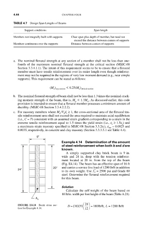
9"
Example 4.14 Determination of the amount
of steel reinforcement when both b and d are
known.
A simply supported clay brick beam is 9 in.
wide and 24 in. deep with the tension reinforce-
ment located at 20 in. from the top of the beam
(Fig. E4.14). The beam has an effective span of 16 ft
20" and carries a service live load of 1200 lb/ft in addition
24" to its own weight. Use ′ f = 2500 psi and Grade 60
m
steel. Determine the flexural reinforcement required
for this beam.
Solution
Calculate the self-weight of the beam based on
10 lb/in. width per foot height of the beam (Table A.21).
A s
FIGURE E4.14 Beam cross sec- D = ( )( ) 9 ⎛ 24 ⎞ = 180lb/ft, L = 1200 lb/ft
10
tion for Example 4.14. ⎝ 12 ⎠