
Page 175 - Design of Reinforced Masonry Structures
P. 175
DESIGN OF REINFORCED MASONRY BEAMS 4.39
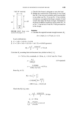
7.63'' (8'' nominal) a. Check if the beam is adequate to carry the load.
b. During the construction of this beam, it was found
that No. 9 bar was not available and it was decided
to use either one No. 10 or one No. 11 bar with the
(erroneous) assumption that larger amount of steel
would only make the beam stronger. Determine if
d = 20''
24'' the beam would be satisfactory using either No. 10
or No. 11 bar in lieu of one No. 9 bar provided for
1#9 in the design.
Solution
FIGURE E4.13 Beam cross
section for Example 4.13. a. Calculate the required moment strength moment, M .
u
D = 1.0 k/ft, L = 1.75 k/ft, L = 12 ft
Load combinations:
1. U = 1.4D = 1.4(1.0) = 1.4 k/ft
2. U = 1.2D + 1.6L = 1.2(1.0) + 1.6(1.75) = 4.0 k/ft (governs)
40 12)
M = wL 2 = (.) ( 2 = 72 k-ft
u
u
8 8
Calculate M assuming that reinforcement has yielded so that f ≥ f .
n s y
2
b = 7.63 in. (8 in. nominal), d = 20 in., A = 1.0 in (one No. 9 bar).
s
Af
a = sy (4.9 repeated)
.
080 fb ′
m
a = (10 60. )( ) = 655 in
.
.
.
080 (15. )(763. )
From Eq. (4.12)
⎛ a ⎞
M = A f ⎝ d − ⎠ 2
s y
n
⎛
.
)( )
= (1 0 60 20 − 655 ⎞
.
⎝ 2 ⎠
= 1003.5 k-in. = 83 63 k-ft
5
.
Check the M / V d ratio.
u v
u
4 0 12 0.)
u
V = wL = (.) ( = 24 kips
u
2 2
d = d = 20 in.
v
M (72 )( )
12
u = = .18 > .10
Vd (24 )(20 )
uv