
Page 170 - Design of Reinforced Masonry Structures
P. 170
4.34 CHAPTER FOUR
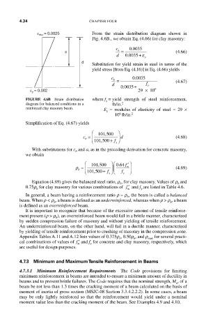
ε mu = 0.0025 From the strain distribution diagram shown in
Fig. 4.6B., we obtain Eq. (4.66) for clay masonry:
.
c 0 0035
c b = (4.66)
d 0 0035 + ε
.
y
d
Substitution for yield strain in steel in terms of the
yield stress [from Eq. (4.16)] in Eq. (4.66) yields
.
c b = 0 0035
d + f y (4.67)
.
0 0035
ε y = 0.002 29 × 10 6
FIGURE 4.6B Strain distribution where f = yield strength of steel reinforcement,
y
diagram for balanced conditions in a lb/in. 2
reinforced clay masonry beam. E = modulus of elasticity of steel = 29 ×
s
6
10 lb/in. 2
Simplification of Eq. (4.67) yields
⎛ 101 500 ⎞
,
c = ⎜ ⎟ d (4.68)
b + f ⎠
⎝ 101 500, y
With substitutions for c and a, as in the preceding derivation for concrete masonry,
b
we obtain
⎛ ⎞ ⎛ 064. f ′ ⎞
,
ρ = ⎜ 101 500 ⎟ ⎜ m ⎟ (4.69)
b
⎝ 101 500, + f y ⎠ ⎝ f y ⎠
Equation (4.69) gives the balanced steel ratio, r , for clay masonry. Values of r and
b
b
0.75r for clay masonry for various combinations of ′ f and f are listed in Table 4.6.
b
y
m
In general, a beam having a reinforcement ratio r = r , the beam is called a balanced
b
beam. When r < r , a beam is defined as an underreinforced, whereas when r > r , a beam
b
b
is defined as an overreinforced beam.
It is important to recognize that because of the excessive amount of tensile reinforce-
ment present (r > r ), an overreinforced beam would fail in a brittle manner, characterized
b
by sudden compression failure of masonry and without yielding of tensile reinforcement.
An underreinforced beam, on the other hand, will fail in a ductile manner, characterized
by yielding of tensile reinforcement prior to crushing of masonry in the compression zone.
Appendix Tables A.11 and A.12 lists values of 0.375r , 0.50r , and r max for several practi-
b
b
cal combinations of values of ′ f and f for concrete and clay masonry, respectively, which
y
m
are useful for design purposes.
4.7.3 Minimum and Maximum Tensile Reinforcement in Beams
4.7.3.1 Minimum Reinforcement Requirements The Code provisions for limiting
minimum reinforcement in beams are intended to ensure a minimum amount of ductility in
beams and to prevent brittle failures. The Code requires that the nominal strength, M , of a
n
beam be not less than 1.3 times the cracking moment of a beam calculated on the basis of
moment of inertia of gross section (MSJC-08 Section 3.3.4.2.2.2). In some cases, a beam
may be only lightly reinforced so that the reinforcement would yield under a nominal
moment value less than the cracking moment of the beam. See Examples 4.9 and 4.10.