
Page 168 - Design of Reinforced Masonry Structures
P. 168
4.32 CHAPTER FOUR
b The expressions for the balanced ratios for concrete and clay
masonry can be derived form Eq. (4.55) as follows:
1. Concrete masonry:
e mu = 0.0025 (4.56)
Substituting e = 0.0025 for concrete masonry, e = e for
h N.A. mu s y
strain in steel reinforcement, and writing c = c in Eq. (4.55),
b
we obtain the relationship between the depth of neutral axis
and the effective beam depth at the balanced conditions as
given by Eq. (4.57):
A s
.
c b = 0 0025 (4.57)
.
(a) d 0 0025 + ε y
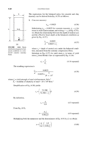
FIGURE 4.6A Strain
distribution diagram for bal- where c = depth of neutral axis under the balanced condi-
b
anced conditions in a rein- tion, measured from the extreme compression fibers.
forced concrete masonry Substitute in Eq. (4.57) for yield strain e in terms of yield
beam. y
stress f from Hooke’s law as expressed by Eq. (4.16):
y
f
ε = y (4.16 repeated)
y
E s
The resulting expression is
c 0 0025
.
b = (4.58)
d + f y
.
0 0025
29 × 10 6
where f = yield strength of steel reinforcement, lb/in. 2
y
6
E = modulus of elasticity of steel = 29 × 10 lb/in. 2
s
Simplification of Eq. (4.58) yields
⎛ ⎞
,
c = ⎜ 72 500 ⎟ d (4.59)
b
⎝ 72 500, + f ⎠
y
By definition,
c = 08 (4.5 repeated)
a
b
.
From Eq. (4.9),
Af
a = sy (4.9 repeated)
080 fb ′
.
m
Multiplying both the numerator and the denominator of Eq. (4.9) by d, we obtain
a = ⎛ A ⎞ ⎛ fd ⎞ (4.60)
y
s
⎝ bd ⎠ ⎜ ⎝ 080. f ′ ⎠ ⎟
m