
Page 169 - Design of Reinforced Masonry Structures
P. 169
DESIGN OF REINFORCED MASONRY BEAMS 4.33
Substitution of ρ = Abd from Eq. (4.37) in Eq. (4.60) yields
/
s
ρ fd
a = y (4.61)
080 f ′
.
m
Combining Eqs. (4.5) and (4.61), we obtain
ρ fd
c = y (4.62)
b
080 080 f ′)
.
(
.
m
Equating the values of c from Eqs. (4.59) and (4.62), we obtain
b
⎛ ρ f ⎞ ⎛ 72 500 ⎞
,
y
⎜ ⎝ 080 080) f ′ ⎠ ⎟ d = ⎜ ⎝ 72 500 + f ⎠ ⎟ ⎠ d (4.63)
.
,
.
(
y
m
Substitution of r = r in Eq. (4.63) yields
b
⎛ 72 500 ⎞ ⎛ 064. f ′ ⎞
,
ρ = ⎜ ⎟ ⎜ m ⎟ (4.64)
b
⎝ 72 500, + f y ⎠ ⎝ f y ⎠
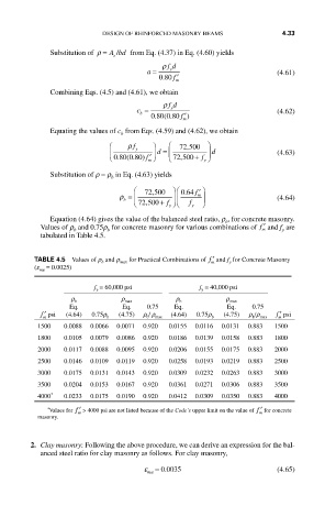
Equation (4.64) gives the value of the balanced steel ratio, r , for concrete masonry.
b
Values of r and 0.75r for concrete masonry for various combinations of ′ f and f are
b
m
b
y
tabulated in Table 4.5.
TABLE 4.5 Values of r b and r max for Practical Combinations of ′ f and f y for Concrete Masonry
m
(e = 0.0025)
mu
f y = 60,000 psi f y = 40,000 psi
r max
r b r b r max
Eq. Eq. 0.75 Eq. Eq. 0.75
′ f psi (4.64) 0.75r (4.75) (4.64) 0.75r (4.75) ′ f psi
b
b
m b r / r max b r /r max m
1500 0.0088 0.0066 0.0071 0.920 0.0155 0.0116 0.0131 0.883 1500
1800 0.0105 0.0079 0.0086 0.920 0.0186 0.0139 0.0158 0.883 1800
2000 0.0117 0.0088 0.0095 0.920 0.0206 0.0155 0.0175 0.883 2000
2500 0.0146 0.0109 0.0119 0.920 0.0258 0.0193 0.0219 0.883 2500
3000 0.0175 0.0131 0.0143 0.920 0.0309 0.0232 0.0263 0.883 3000
3500 0.0204 0.0153 0.0167 0.920 0.0361 0.0271 0.0306 0.883 3500
4000 * 0.0233 0.0175 0.0190 0.920 0.0412 0.0309 0.0350 0.883 4000
*
Values for ′ f > 4000 psi are not listed because of the Code’s upper limit on the value of ′ f for concrete
m m
masonry.
2. Clay masonry: Following the above procedure, we can derive an expression for the bal-
anced steel ratio for clay masonry as follows. For clay masonry,
e = 0.0035 (4.65)
mu