Page 173 - Design of Reinforced Masonry Structures
P. 173

DESIGN OF REINFORCED MASONRY BEAMS          4.37

         compressive strains will not exceed their ultimate values, and that the compressive zone
         of the member would not crush before the tensile reinforcement develops inelastic strain
         consistent with the curvature ductility requirements.
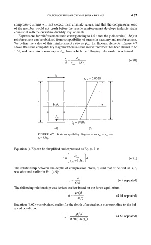
           Expressions for reinforcement ratio corresponding to 1.5 times the yield strain (1.5e ) in
                                                                      y
         reinforcement can be obtained from compatibility of strains in masonry and reinforcement.
         We define the value of this reinforcement ratio as r max  for flexural elements. Figure 4.7
         shows the strain compatibility diagram wherein strain in reinforcement has been shown to be
         1.5e  and the strain in masonry as e , from which the following relationship is obtained:
                                  mu
            y
                                   c     ε
                                     =    mu                         (4.70)
                                   d  ε  +15.  ε
                                       mu    y
                              b
                                             ε mu  = 0.0035


                                                     c
                                                            d
                     h
                             N.A.


                              A s
                                       ε y = 0.002
                              (a)               (b)
                     FIGURE 4.7  Strain compatibility diagram when e m  = e mu  and
                     e s  = 1.5e y .

         Equation (4.70) can be simplified and expressed as Eq. (4.71):
                                     ⎛  ε    ⎞
                                         mu
                                  c =  ⎜ ⎝ ε mu +15.  ε y ⎠ ⎟  d     (4.71)

         The relationship between the depths of compression block, a, and that of neutral axis, c,
         was obtained earlier in Eq. (4.9):
                                     c =  a                    (4.9 repeated)
                                         08
                                          .
         The following relationship was derived earlier based on the force equilibrium
                                         ρ fd
                                     a =   y                  (4.61 repeated)
                                         .
                                        080 f ′
                                            m
         Equation (4.62) was obtained earlier for the depth of neutral axis corresponding to the bal-
         anced condition:
                                         ρ fd
                                   c =     y                  (4.62 repeated)
                                   b
                                         (
                                       .
                                      080 080  f ′)
                                           .
                                              m
   168   169   170   171   172   173   174   175   176   177   178