
Page 288 - Design of Reinforced Masonry Structures
P. 288
5.8 CHAPTER FIVE
For h/r > 99
m ( )
P = 080[ P′ + P′] 70 r 2
.
n s
h
70
r
= 080 080 f ′( A − A ) + fA st ] ( ) 2 (5.9)
)
[ .
.
st
y
m
n
h
It is noted that for the slenderness ratio h′/r = 99, Eqs. (5.8) and (5.9) give the same values
of P , for when h/r = 99,
n
2
⎤
⎡ ( ) ⎥ ( ) 2
70r
h
⎢ ⎣ 1− 140r ⎦ = h = 05 .
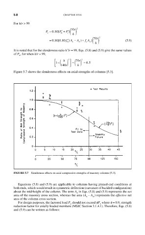
Figure 5.7 shows the slenderness effects on axial strengths of columns [5.3].
FIGURE 5.7 Slenderness effects on axial compressive strengths of masonry columns [5.3].
Equations (5.8) and (5.9) are applicable to columns having pinned-end conditions at
both ends, which would result in symmetric deflection (curvature of buckled configuration)
about the mid-height of the column. The term A in Eqs. (5.8) and (5.9) represents the net
n
area of the masonry cross section, whereas the area (A – A ) represents the effective net
st
n
area of the column cross section.
For design purposes, the factored load P should not exceed fP where f = 0.9, strength
n
u
reduction factor for axially loaded members (MSJC Section 3.1.4.1). Therefore, Eqs. (5.8)
and (5.9) can be written as follows: