
Page 295 - Design of Reinforced Masonry Structures
P. 295
COLUMNS 5.15
high concrete masonry units for a column and ¼ in. ties for the longitudinal reinforcement, the
tie spacing should be 8 in. even though 48 times the tie diameter gives 48(¼) = 12 in. This is
because 12 in. spacing would not match the coursing height of 8 in. Similarly, if one were to
use 3 /8-in.-diameter ties, the spacing should be 8 or 16 in. (24-in. tie spacing would exceed
the 48 times the tie diameter when using a 3 /8-in.-diameter tie). Any other tie spacing, say
10 or 15 in., would not match coursing, and might necessitate cutting of the masonry units
at the jobsite, which would slow down the progress of work.
1. Lateral ties are to be arranged to comply with the following requirements:
a. All corner bars and alternate longitudinal bars are laterally supported by the corner
of a complete tie having an included angle of not more than 135°.
b. No bar can be farther than 6 in. clear on each side along the lateral tie from such a
laterally supported bar. See Fig. 5.6.
c. Where longitudinal bars are placed around the perimeter of a circle, a complete cir-
cular tie is permitted. The required lap length for a circular tie is 48 tie diameters.
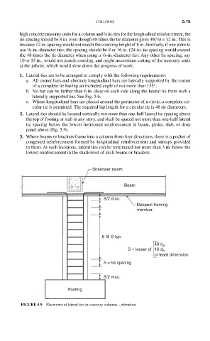
2. Lateral ties should be located vertically not more than one-half lateral tie spacing above
the top of footing or slab in any story, and shall be spaced not more than one-half lateral
tie spacing below the lowest horizontal reinforcement in beam, girder, slab, or drop
panel above (Fig. 5.9).
3. Where beams or brackets frame into a column from four directions, there is a pocket of
congested reinforcement formed by longitudinal reinforcement and stirrups provided
in them. At such locations, lateral ties can be terminated not more than 3 in. below the
lowest reinforcement in the shallowest of such beams or brackets.
Shallower beam
Beam
S/2 max.
Deepest framing
member
6 @ S typ.
S = lesser of 16 d b
48 t tie
or least dimension
S = tie spacing
S/2 max.
Footing
FIGURE 5.9 Placement of lateral ties in masonry columns—elevation.