
Page 296 - Design of Reinforced Masonry Structures
P. 296
5.16 CHAPTER FIVE
Example 5.1 Maximum bar size for longitudinal reinforcement.
Determine the maximum size for longitudinal reinforcement that can be used for a
column built from 8 × 8 × 16 standard CMU.
Solution
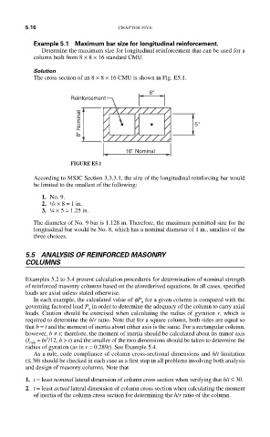
The cross section of an 8 × 8 × 16 CMU is shown in Fig. E5.1.
6''
Reinforcement
8'' Nominal 5''
16'' Nominal
FIGURE E5.1
According to MSJC Section 3.3.3.1, the size of the longitudinal reinforcing bar would
be limited to the smallest of the following:
1. No. 9.
2. 1 /8 × 8 = 1 in.
3. ¼ × 5 = 1.25 in.
The diameter of No. 9 bar is 1.128 in. Therefore, the maximum permitted size for the
longitudinal bar would be No. 8, which has a nominal diameter of 1 in., smallest of the
three choices.
5.5 ANALYSIS OF REINFORCED MASONRY
COLUMNS
Examples 5.2 to 5.4 present calculation procedures for determination of nominal strength
of reinforced masonry columns based on the aforederived equations. In all cases, specified
loads are axial unless stated otherwise.
In each example, the calculated value of fP for a given column is compared with the
n
governing factored load P in order to determine the adequacy of the column to carry axial
u
loads. Caution should be exercised when calculating the radius of gyration r, which is
required to determine the h/r ratio. Note that for a square column, both sides are equal so
that b = t and the moment of inertia about either axis is the same. For a rectangular column,
however, b ≠ t; therefore, the moment of inertia should be calculated about its minor axis
3
(I min = bt /12, b > t) and the smaller of the two dimensions should be taken to determine the
radius of gyration (as in r = 0.289t). See Example 5.4.
As a rule, code compliance of column cross-sectional dimensions and h/t limitation
(≤ 30) should be checked in each case as a first step in all problems involving both analysis
and design of masonry columns. Note that
1. t = least nominal lateral dimension of column cross section when verifying that h/t ≤ 30.
2. t = least actual lateral dimension of column cross section when calculating the moment
of inertia of the column cross section for determining the h/r ratio of the column.