
Page 440 - Design of Reinforced Masonry Structures
P. 440
7.2 CHAPTER SEVEN
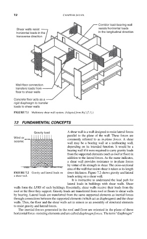
Corridor load-bearing wall
Shear walls resist resists horizontal loads
horizontal loads in the in the longitudinal direction
transverse direction
Wall-floor connection
transfers loads from
floor to shear walls
Concrete floor acts as a
rigid diaphragm to transfer
loads to shear walls
FIGURE 7.1 Multistory shear wall system. (Adapted from Ref. [7.1].)
7.2 FUNDAMENTAL CONCEPTS
Gravity load A shear wall is a wall designed to resist lateral forces
parallel to the plane of the wall. These forces are
Wind or commonly referred to as in-plane forces. A shear
seismic
wall may be a bearing wall or a nonbearing wall,
depending on its intended function. It would be a
bearing wall if it were required to carry gravity loads
from the supported elements (such as roof or floor) in
addition to the lateral forces. As the name indicates,
a shear wall provides resistance to in-plane forces
by virtue of its strength in shear. The cross-sectional
area of the wall that resists shear is taken as its length
FIGURE 7.2 Gravity and lateral loads on times thickness. Figure 7.2 shows gravity and lateral
a shear wall. loads acting on a shear wall.
It is instructive to understand the load path for
lateral loads in buildings with shear walls. Shear
walls form the LFRS of such buildings. Essentially, shear walls receive their loads from the
roof or the floor they support. Gravity loads are transferred from roof or floors to shear walls
by bearing. Lateral loads are transferred from the same supported elements as inertial forces
through connections between the supported elements (which act as diaphragms) and the shear
walls. Thus, the floor and the shear walls act in unison as an assembly of structural elements
to resist gravity and lateral forces.
The inertial forces generated in the roof and floor are oriented in the plane of these
horizontal force–resisting elements and are called diaphragm forces. The term “diaphragm”