
Page 441 - Design of Reinforced Masonry Structures
P. 441
SHEAR WALLS 7.3
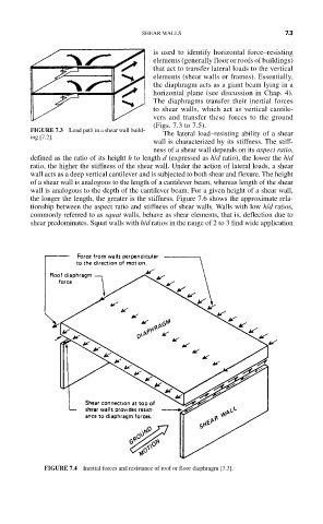
is used to identify horizontal force–resisting
elements (generally floor or roofs of buildings)
that act to transfer lateral loads to the vertical
elements (shear walls or frames). Essentially,
the diaphragm acts as a giant beam lying in a
horizontal plane (see discussion in Chap. 4).
The diaphragms transfer their inertial forces
to shear walls, which act as vertical cantile-
vers and transfer these forces to the ground
(Figs. 7.3 to 7.5).
FIGURE 7.3 Load path in a shear wall build- The lateral load–resisting ability of a shear
ing [7.2].
wall is characterized by its stiffness. The stiff-
ness of a shear wall depends on its aspect ratio,
defined as the ratio of its height h to length d (expressed as h/d ratio), the lower the h/d
ratio, the higher the stiffness of the shear wall. Under the action of lateral loads, a shear
wall acts as a deep vertical cantilever and is subjected to both shear and flexure. The height
of a shear wall is analogous to the length of a cantilever beam, whereas length of the shear
wall is analogous to the depth of the cantilever beam. For a given height of a shear wall,
the longer the length, the greater is the stiffness. Figure 7.6 shows the approximate rela-
tionship between the aspect ratio and stiffness of shear walls. Walls with low h/d ratios,
commonly referred to as squat walls, behave as shear elements, that is, deflection due to
shear predominates. Squat walls with h/d ratios in the range of 2 to 3 find wide application
FIGURE 7.4 Inertial forces and resistance of roof or floor diaphragm [7.3].