
Page 446 - Design of Reinforced Masonry Structures
P. 446
7.8 CHAPTER SEVEN
Shear walls meeting each other at right angles (Fig. 7.1) result in flanged configura-
tions and are referred to as flanged walls. In such cases, a portion of the intersecting
wall can be treated as a flange of the shear wall (e.g., as an I-section or a T-section).
Such walls are normally required to resist earthquake forces in both principal directions
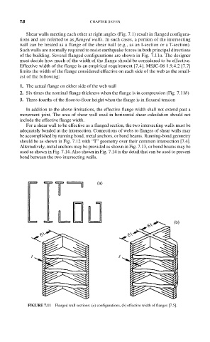
of the building. Several flanged configurations are shown in Fig. 7.11a. The designer
must decide how much of the width of the flange should be considered to be effective.
Effective width of the flange is an empirical requirement [7.4]. MSJC-08 1.9.4.2 [7.7]
limits the width of the flange considered effective on each side of the web as the small-
est of the following:
1. The actual flange on either side of the web wall
2. Six times the nominal flange thickness when the flange is in compression (Fig. 7.11b)
3. Three-fourths of the floor-to-floor height when the flange is in flexural tension
In addition to the above limitations, the effective flange width shall not extend past a
movement joint. The area of shear wall used in horizontal shear calculation should not
include the effective flange width.
For a shear wall to be effective as a flanged section, the two intersecting walls must be
adequately bonded at the intersection. Connections of webs to flanges of shear walls may
be accomplished by running bond, metal anchors, or bond beams. Running-bond geometry
should be as shown in Fig. 7.12 with “T” geometry over their common intersection [7.4].
Alternatively, metal anchors may be provided as shown in Fig. 7.13, or bond beams may be
used as shown in Fig. 7.14. Also shown in Fig. 7.14 is the detail that can be used to prevent
bond between the two intersecting walls.
FIGURE 7.11 Flanged wall sections: (a) configurations, (b) effective width of flanges [7.5].