
Page 449 - Design of Reinforced Masonry Structures
P. 449
SHEAR WALLS 7.11
The determination of rigidity of a shear wall is akin to determining the stiffness of a
beam. For determining in-plane deflections, a shear wall may be visualized as vertical
flexural element such that
1. Its length is analogous to the depth of a rectangular beam.
2. Its height is equal to the length of the beam.
3. The wall thickness is analogous to the width of the rectangular beam.
Because of the large depth, the deflection of a shear wall (a vertical beam) is the sum of
two components: (1) deflection due to flexure and (2) deflection due to shear. The recipro-
cal of the total deflection is defined as the rigidity of the wall. Expressions for deflections
are determined based on principles of structural mechanics (for deflections of beams), a
topic well covered in texts on structural analysis and not discussed here. However, a brief
review of these principles is presented in the next section.
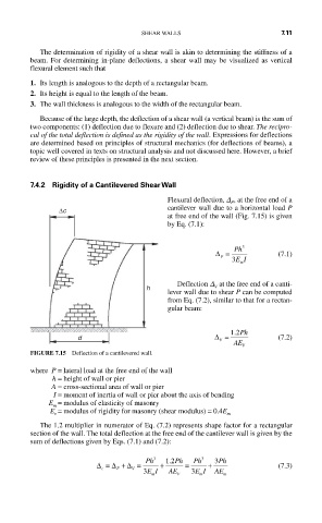
7.4.2 Rigidity of a Cantilevered Shear Wall
Flexural deflection, D , at the free end of a
F
cantilever wall due to a horizontal load P
∆c
at free end of the wall (Fig. 7.15) is given
by Eq. (7.1):
∆ = Ph 3 (7.1)
F
3 EI
m
Deflection D at the free end of a canti-
h V
lever wall due to shear P can be computed
from Eq. (7.2), similar to that for a rectan-
gular beam:
.
d ∆ = 12 Ph (7.2)
V
AE
V
FIGURE 7.15 Deflection of a cantilevered wall.
where P = lateral load at the free end of the wall
h = height of wall or pier
A = cross-sectional area of wall or pier
I = moment of inertia of wall or pier about the axis of bending
E = modulus of elasticity of masonry
m
E = modulus of rigidity for masonry (shear modulus) = 0.4E
v m
The 1.2 multiplier in numerator of Eq. (7.2) represents shape factor for a rectangular
section of the wall. The total deflection at the free end of the cantilever wall is given by the
sum of deflections given by Eqs. (7.1) and (7.2):
.
∆ = ∆ + ∆ = Ph 3 + 12 Ph = Ph 3 + 3 Ph (7.3)
c F V
3 EI AE 3 EI AE
m V m m