
Page 452 - Design of Reinforced Masonry Structures
P. 452
7.14 CHAPTER SEVEN
Similarity between Eqs. (7.10) and (7.16) may be noted. In general both equations can
be expressed in a general form as Eq. (7.17):
R = R (7.17)
r
Et
m
where R = rigidity of the wall.
Note that relative rigidity, R , given by Eq. (7.15) is a function of h/d ratio only; there-
r
fore, as explained earlier, this expression can be used to determine the relative rigidity of
walls of any thickness and material (e.g., concrete). The values of relative rigidity given by
Eq. (7.15) for large aspect ratios (i.e., large values of h/d-ratio) are relatively small. Therefore,
in order to preserve accuracy of these small values to three places of decimals, the right side of
Eq. (7.15) is multiplied by an arbitrary factor of 10, the resulting expression being
R = 1 (7.18)
r
⎡ ⎛ h ⎞ 3 ⎛ h ⎞ ⎤
⎢ 01 . ⎝ + 03 . ⎝ ⎥
⎣ d ⎠ d ⎠ ⎦
Eq. (7.18) is commonly used to calculate the relative rigidity of fixed-ended shear walls.
Values of relative rigidities of walls for various aspect ratios [determined from Eq. (7.18)]
are listed in Table A.27.
Examples 7.1 and 7.2 illustrate calculations for determining the rigidity and relative
rigidity for cantilevered and fixed-ended shear walls, respectively. In design problems, all
masonry walls at a given level of a building are of the same compressive strength and thick-
ness. Therefore, relative rigidity can be used for rigid diaphragm-shear wall analysis.
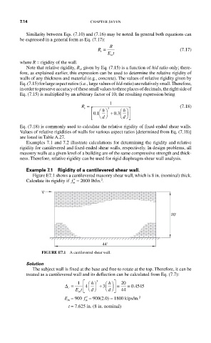
Example 7.1 Rigidity of a cantilevered shear wall.
Figure E7.1 shows a cantilevered masonry shear wall, which is 8 in. (nominal) thick.
2
Calculate its rigidity if ′ f = 2000 lb/in. .
m
V
20'
44'
FIGURE E7.1 A cantilevered shear wall.
Solution
The subject wall is fixed at the base and free to rotate at the top. Therefore, it can be
treated as a cantilevered wall and its deflection can be calculated from Eq. (7.7):
∆ = 1 ⎡ ⎢ 4 ⎛ h ⎞ 3 + 3 ⎛ h ⎞ ⎤ ⎥ = 20 = 0 4545
.
c ⎝ d ⎠ ⎝ d ⎠
m ⎣
Et ⎦ 44
E = 900 ′ f = 900(2.0) = 1800 kips/in. 2
m
m
t = 7.625 in. (8 in. nominal)